Continue to Site

Eng-Tips is the largest engineering community on the Internet

Intelligent Work Forums for Engineering Professionals

  • Congratulations cowski on being selected by the Eng-Tips community for having the most helpful posts in the forums last week. Way to Go!

Modal Test Cantilever Beam - Stinger Attachment

Status
Not open for further replies.

dsengine

Mechanical
Feb 5, 2005
8
Hi there,

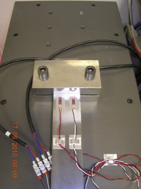
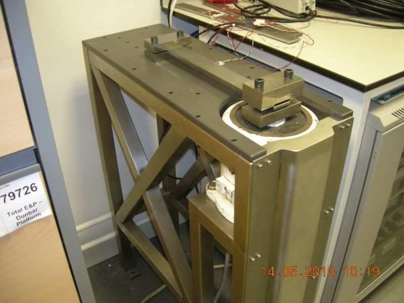
I'm attempting to perform a modal test on a cantilever beam. The idea is to measure the strain at the constrained end using strain gauges, with output to a datalogger. A signal generator and shaker will provide the sinusoidal applied force at the tip. My question relates to how best to transmit this force to the beam.

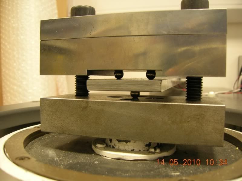
Currently ball bearings transmit the force to the tip end but the clamp around the ball bearings is fairly massive and I'm worried this will produce inaccurate results. It appears that thin "stingers" might be the solution but I'm not sure how these are attached to the beam. I realise the object is to keep the applied transverse forces to a minimum so that the driving force is purely axial.

Would a tapped plug in the beam be a solution and screwed into the stinger? Or a hole right through the beam and clamped at either end? Or would an epoxy adhesive be more suitable?

Appreciate any advice you can provide. Many thanks in advance.
 
Replies continue below

Recommended for you

Any of the above should work. Compare your results with those from an impact hammer to see if you've got a good solution. The flexibility of the stinger, and its alignment with the shaker axis, are the keys to success. Incidentally I assume you are mounting your force gauge between the stinger and the test object?

The details depend on the size of the beam.

The ball bearing idea sounds awful.

A photo of your test setup may inspire useful comment.


Cheers

Greg Locock


New here? Try reading these, they might help FAQ731-376
 
Currently there are only 2 or 4 strain gauges at the fixed end and no force gauge (which is basically a strain gauge anyway) at the tip. It's mainly to be used as a calibration device for other instruments so I'm not too fussed about determining the applied force - the main difficulty so far has been getting it to resonate at higher frequency modes (4th mode onwards).

I'm worried if I start putting holes through the beam and clamping then it will constrain the beam and apply an unwanted (and unmeasured) moment.

Photos of current setup are included below. Thanks again.

StrainGauge.jpg


VP3.jpg


shakerhead.jpg
 
Hmmm ok...to me a modal test would be to do a sin sweep and excited it at the "base" of the cantilever beam and not at the tip. Unless that is where the forced frequency is being applied in the field and then I'm wrong.

Tobalcane
"If you avoid failure, you also avoid success."
 
Oh, also, a modal test is to find the first Fn and shape and then the subsequent frequencies and shapes. But, what it sounds like is that you are trying to find the stress at the base of the cantilever beam. This is more of beam stress analysis. You can calculate the Fn of this beam and then calculate the deflection at the tip. Deflect the tip and you can read your stress from there. Also, there has been many studies of cantilever beam stress analysis and can be calculated out. You can do this to correlate if you like.

I think with one end fixed and exiting the other end will give you different results than exciting just at the fixed end. With this set up, I don't think you can call this a cantilever beam modal test, but one fixed end and one pinned end study.

Tobalcane
"If you avoid failure, you also avoid success."
 
A nice stinger that would be about the right size for your test would be a piano wire about 8 inches long, under tension. However it may go into resonance in its own right.

The standard stinger we use is brass rod, 5/32" OD, thinned to about 1/8" or less in two places at each end. Again length is 6-8".

Your current setup is ingenious but unlike anything I have ever used and I would expect it to affect your results in many odd ways.

As Twoballcane implies, exciting the tip of a cantilever will produce a response dominated by the first mode. In theory you should be OK.

Incidentally Blevins says the first four modal frequencies are in the ratio of the squares of these numbers

1.8 4.6 7.8 11

for a free/clamped beam.


Cheers

Greg Locock


New here? Try reading these, they might help FAQ731-376
 

hardly a free-response test of a cantilever.

what level of precision are you seeking?

 
Status
Not open for further replies.

Part and Inventory Search

Sponsor