Continue to Site

Eng-Tips is the largest engineering community on the Internet

Intelligent Work Forums for Engineering Professionals

  • Congratulations cowski on being selected by the Eng-Tips community for having the most helpful posts in the forums last week. Way to Go!

Combined Controls Extension 4

Status
Not open for further replies.

axym

Industrial
Apr 28, 2003
1,043
Here is Figure 8-24 from Y14.5-2009, with an additional position tolerance added:

Fig_8-24_with_Boundary_Orientation_e9erl2.png


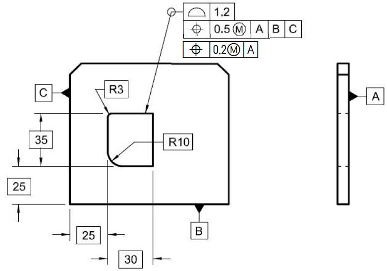
The additional callout refines the relationship of the feature to Datum A.

Is this a valid application? ;^)

Evan Janeshewski

Axymetrix Quality Engineering Inc.
 
Replies continue below

Recommended for you

semiond,

If you wanted to convert the combination in Fig. 8-24 to a single profile tolerance to A|B|C, I think that the tolerance value would have to be 2.85. So the FCF would be [PRF|2.85(U)0.85|A|B|C].

Evan Janeshewski

Axymetrix Quality Engineering Inc.
 
Evan, i'm left floundering about 2.85.
Here is my explanation to the numbers:

If we consider the Virtual Condition (max. material) boundary and the Resultant Condition (min. material) boundary, i think the distance between them is 1.45; the RC is at distance of 0.6 from the true profile. The VC is at distance of 0.6 (half profile) + 0.25 (half position) from the true profile. Total width of the profile tolerance zone (per my proposed alternative) is 1.45. The portion allowed to be outside the material relative to the true profile is 0.85.

Here is the graphical depiction of the tolerance zones from the bottom of the figure:
20180628_172759_ei2xl8.jpg
 
semiond,
Thanks for the understanding - it just seemed like an obvious thing I should have caught and I try to put a decent amount of thought into my questions, but you are right about this being enrichment.

I think typically when we refer to "functional gauges" we mean a fixed gauge. An RFS gauge would have to be adjustable.

As far as your numbers I see where Evan is coming from but I think it actually falls between both of your proposals - I would say the total tolerance zone should actually be 1.7 as the additional position tolerance would allow the entire 1.2 original zone to shift 0.25 up to the "positional boundary" which actually would increase the size of the tolerance zone on both sides - so the total zone increases by the full position tolerance. So in this case it would still be an equally disposed profile tolerance of 1.7 - at least I think.
 
I think i'm also starring starting to understand where Evan is getting at and per my last calculation it is actually 2.9!

Consider the widest feature allowed per the 1.2 profile FCF segment at the direction of 30 basic dimension, and put it in a location where it contacts the positional boundary on the right side. Now check where the left side of the as-produced profile reached. That scenario is widening what i previoulsy was considering the RC boundary.

This is getting interesting...
 
semiond,

I think you may be correct, the combined control is really throwing me off as I'm not considering the bonus tolerances allowed by the MMC position callout for a feature of LMC size. Its safe to say though that this would not be "equivalent" because as opposed to the profile/position combined tolerance a single profile control of this size would allow a much larger (and smaller) feature. This would have to be changed to a MSS or composite profile tolerance to get a similar control - albeit without the ability to apply MMC/LMC and without available bonus tolerance.
 
Chez311:
Here is what i would currently consider a tolerancing scheme exactly equivalent to the one shown in fig. 8-24:

[[profile]][2.9(U)0.85][A][C]
[[Profile]][1.2]

The second segment is of course a refinement of the first one.

I even think it could be gaged/inspected in the same way despite of the fact that technically the term MMC can't be used in regards to the composite profile.

Objections?
 
semiond,

I'm trying to think of a way to disprove that as it doesn't seem like we should be able to get the same result without position at MMC, however it looks like the tolerance zone would behave in almost exactly the same way - down to replicating the behavior of bonus tolerance afforded by the position control in the example 8-24, without technically providing bonus tolerance obviously as MMC/LMC cannot be applied.

Perhaps it comes down to the fact that the tolerances in the FCF's must be exactly matched to provide the proper behavior - any mismatch (ie: one or both too large/too small vs. the other or improperly distributed) and the behavior will be different vs. the boundary concept provided by combined position at MMC/profile tolerance. This will work out to a pseudo-"bonus tolerance" that will not work out correctly or intuitively what we're used to with standard MMC/LMC bonus tolerance with position.

Anybody else care to comment on this - maybe I'm missing something? Evan/CH/Belanger/pmarc?
 
chez311,

Here is how I see it:

I used slightly more regular contour than the one in fig. 8-24, but I believe that this should not change anything when it comes to drawing a general conclusion.

There is one more interesting observation to make, in my opinion. In the profile/position combo scheme, if one or both tolerance values are big enough to allow the actual contour to rotate more or less freely about the MMB boundary (in a similar way to what I have shown in the attached document), this may lead to some unexpected and undesired consequences.
 
pmarc,

Thank you as always for your detailed figures - it definitely clearly shows the interrelationship of the combined callouts. I do wish that the standard had more detail in this area to more clearly explain the behavior that results from using the boundary concept but alas that seems to be a pattern with some of these topics.

That is definitely an interesting note about the unexpected behavior of the combined profile/position control vs. pure profile. My first thought is that this is only really significant when the tolerance is very near the size of the feature (in your figure the tolerance zone width of 2.9 is very nearly half the true profile of 6.0) and becomes proportionally less of an issue as the size of the feature approaches several multiples of the tolerance zone size - for example if your true profile had a size of 30 then this deviation allowed by the position/profile combination vs. pure profile is still present (depending on corner radii as well - a sharp corner limits this significantly), but to a much smaller degree. To this end I think that you have shown that in many use cases the MSS/composite profile control that semiond suggested can very nearly replicate the behavior of a profile/position at MMC control - but not precisely which precludes the ability to treat them the same (ie: with gauging).

HOWEVER - as I think about it more, since profile can be applied to just about any shape one can imagine, I would think that there is some shapes with generous radii or nearly circular shapes/sections that some strange and unexpected behavior could be present with either (a) profile/position combined control or (b) an overly generous profile tolerance (with either profile/position or MSS/composite profile) which means that the designer must carefully analyze all the factors when applying such tolerance schemes. As far as I can tell the MSS/composite profile tolerance is the more conservative in most cases.
 
pmarc - isn't the 10.1 value on sheet 2 the size of the Resultant Condition, not the LMB?
 
chez311,
I agree that the bigger the "ratio" of size of the feature to the values of the position and/or profile tolerances, the smaller the effect of the unexpected behavior. I also agree with your HOWEVER part of the reply. Could you just help me understand what the MSS stands for?

EDIT: Nevermind about the meaning of MSS. I figured it stands for Multiple Single Segment.


3DDave,
I decided to use term LMB instead of Resultant Condition just like I used MMB instead of Virtual Condition. I guess I could also call them Inner Boundary and Outer Boundary.*

The key thing here is that the 10.1 dimension is not really the true size of that extreme boundary, regardless of how we will call it. The figure on sheet 3 shows that the extremities of the toleranced feature can reach farther than just 5.05 (10.1/2) from the true position. That is why I think the idea of conversion of profile+position combo to a composite profile by calculating size of the extreme outer boundary based just on a possible translation of the feature is not a good idea - at least not for features other than circles/cylinders.

---------
* In my opinion life would be so much easier if the number of terms used to describe the extreme boundaries of a feature was minimized in the standard. Inner Boundary, Outer Boundary, Virtual Condition, Resultant Condition, Maximum Material Boundary, Least Material Boundary - this is one of the areas in the standard where people trying to understand it could get a severe headache.
 
pmarc, your analysis discovered a very interesting thing (the unexpected behaviour allowed by position).
I must add from the practical aspect, that it is hard for me to imagine a real application that could be intentionally allowed to behave that way.
In my workplace, if the produced product differs visually from what is depicted on the drawing, even if all dimensions are produced within their specified tolerances, the people at the production plant are obligated to ask the designer's approval for the visual discrepancy. I'm not sure if similar procedure is practiced everywhere else, or if this is dictated by some quality assurance standard, but nevertheless...

In direct continuation to the said above i must add, that i maybe biased here, but i think that the combined profile describes the most probable design intent in this case, better than the datumless profile combined with MMC position. It addresses the allowed tolerance zones and the resultant & virtual conditions boundaries directly, whereas in the standard figure the same zones and boundaries are the stack up result of the specified tolerance values and require some work to be discovered. Obviously it also prevents that unexpected behaviour, and i think that it is fair to say that in the manufacturing buisness "unexpected" is almost a synonim to "unwanted".
 
pmarc - seconded; since Virtual Condition was established a while back and Resultant Condition is the opposite, I would have ditched the rest outside of the mathematical definitions standard. They are useful in describing descriptions, like naming the parts of sentences and parts of speech, but less so in the application of these concepts. It just triples the number of terms with no additional clarity to the end user.

Edit because [Submit Post] is just a bit too close to where I wanted the cursor.
 
pmarc,

Yes you are correct - MSS stands for Multiple Single Segment, it was abbreviated in much of the lessons I took on GDnT so its stuck with me that way, apologies for the confusion.

pmarc said:
The figure on sheet 3 shows that the extremities of the toleranced feature can reach farther than just 5.05 (10.1/2) from the true position. That is why I think the idea of conversion of profile+position combo to a composite profile by calculating size of the extreme outer boundary based just on a possible translation of the feature is not a good idea - at least not for features other than circles/cylinders.

Wouldn't that be an example of why the composite profile is the preferable choice? As semiond noted typically unexpected = unwanted and it looks like while maybe not entirely preventing this, composite profile seems to limit some of this behavior if the zone and limits are set up correctly - of course the same result could be had with composite profile if the tolerance zone was made excessively large.
 
I hope it is not too late to get back to Evan's original question about the orientation refinement. What is not so clear to me is - since the 0.2(M)|A position uses the boundary interpretation to refine orientation, how will the boundary look like in this case? If it should be at uniform distance of 0.1 from the MMB of the complex feature, will it not make the positional boundary of the second segment (at uniform distance of 0.25) redundant?


Edit:
I made a check by myself and discovered that the position tolerance WRT datums will not be redundant, because the refinement position boundary floats together with the profile tolerance. However, I also discovered that the resulting tolerance zone of the orientation is not obvious from the specified value and it actually equals the profile tolerance+ half of the position tolerance refinement. Attached is a sketch displaying it. I modified the tolerance values to make the zones more visible:

*profile is within 2.

*position WRT datums A,B,C is within 1.4.

*position as orientation refinement is 1.

Displayed is one possible location of the tolerance zones. The dashed thick lines are the profile tolerance zone, the dashed orange thin profile is the refinement boundary, the continuous internal profile is the virtual condition boundary established by the position tolerance WRT to the datums. Maximum orientation deviation is 2.5. I find the fact that it's not directly accepted from the refinement FCF disturbing.

image001_malxrd.jpg


Edit: if my analysis is correct, the "refinement" tolerance zone ia actually larger than the Profile specification used to define form. Then it is not really a refinement. I would currently answer Evan that it's not a good application since it fails.
 
semiond,

Two things:
1. As you correctly noticed, the MMB boundary created by the position callout wrt A is not redundant because it can translate toghether with the profile tolerance zone. The only relationship to datum plane A that is actually controlled by that callout is perpendicularity. So if the only relationship is perpendicularity, the question is, does it make sense to use position symbol at all?

2. As for your sketch, look at it again and ask yourself what the maximum possible orientation error could be if there was no "position of 1 orientation refinement" callout. And keep in mind that no one said that this extra callout was form refinement. Orientation requirement is what we have been talking about.

* Hopefully you did not edited your post for the third time while I am writing this comment ;-)
 
pmarc,

1. I would say the answer is no. For orienation refinement, my choice would perpendicularity of "each line element", I'm with CH on this matter.

2. I would say the maximum error will be 2, as dictated by the form control (Profile).

* The addition in the bottom of my post under the picture is from a few hours ago. So I hope that your assumption is correct, I didn't edit the post while you were writing the comment :)
 
chez311 said:
Wouldn't that be an example of why the composite profile is the preferable choice? As semiond noted typically unexpected = unwanted and it looks like while maybe not entirely preventing this, composite profile seems to limit some of this behavior if the zone and limits are set up correctly - of course the same result could be had with composite profile if the tolerance zone was made excessively large.

I think that there is a place for both. Composite profile is more stringent requirement, but that does not mean that profile + position @MMC combo should not be the preferable choice in some cases. The combo in case of irregular features of size is a similar technique to applying position @MMC to directly toleranced regular features of size (pins, tabs, holes, slots), except that in case of the combo the size and form is controlled with profile tolerance and not with Rule #1. There are certain risks behind using it (the unexpected behavior under certain specific conditions that we talked about), but that does not always disqualify it.
 
semiond,

1. Perpendicularity of "each line element" does not result in the same geometric requirement as the position/perpendicularity tolerance @MMC wrt A, so I am not sure I understand why you add it to the conversation. In case of perpendicularity of "each line element", regardless of the feature size the amount of available perpendicularity error would have to be the constant. In case of position/perpendicularity tolerance @MMC wrt A the possible amount of perpendicularity error changes (increases) with the increase of the size of the feature.

2. Incorrect. The maximum possible orientation error (for feature at LMC) would be 2.5. I guess you said 2 because you assumed that the profile tolerance zone is perpendicular to datum plane A. That is not what the profile tolerance is saying.
 
I made a typo in my last reply. There should be 2.7 instead of 2.5.
 
Status
Not open for further replies.

Part and Inventory Search

Sponsor