Continue to Site

Eng-Tips is the largest engineering community on the Internet

Intelligent Work Forums for Engineering Professionals

  • Congratulations cowski on being selected by the Eng-Tips community for having the most helpful posts in the forums last week. Way to Go!

Profile of surface combined with dimension tolerancing

Status
Not open for further replies.

Wuzhee

Automotive
Jul 12, 2022
294
Hello everyone,

I'm overwhelmed by the amount of information regarding GD&T profile and I can't seem to find my answer here (or I got exhausted trying to understand all the information)
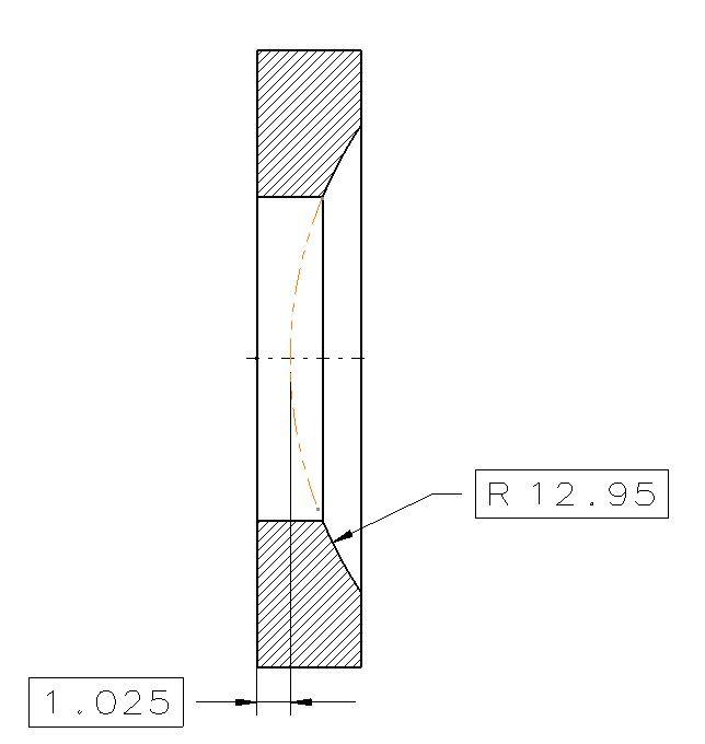
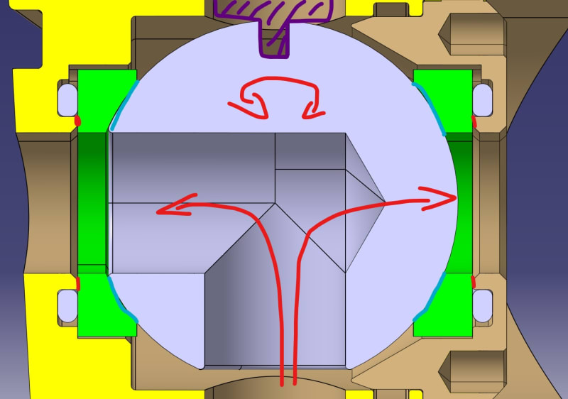
We have a small part with a sphere surface.
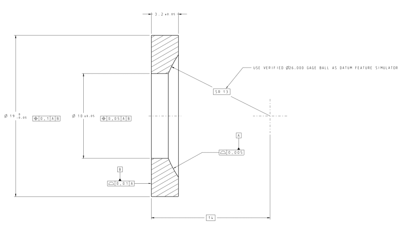
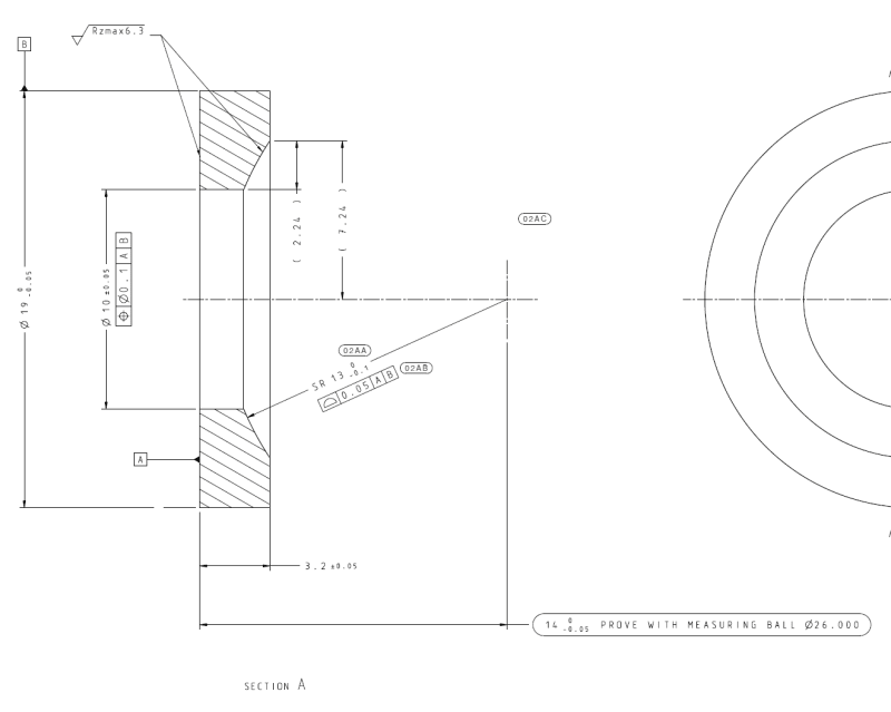
Based on ASME Y14.5-2018 is this dimensioning correct?
I'm currently modeling an assembly with parts at MMC to check for intersections and functionality. But when I looked at this drawing I got confused how to calculate the maximum material condition. (i.e. smallest sphere size)
Is it true when the sphere surface is at it's minimum size, the form has to be perfectly spherical, which is impossible to achieve?
Does the 0.05 profile refine the size tolerance? For me, it's confusing because if I go down in size, for e.g. at 12.92 I could no longer have a 0.05 profile tolerance.

Would it be reasonable to control the size, location and form with only the surface callout and basic dimensions?
Like |profile|0.05|A|B| and |SR13| and theoretical shpere center |14| are basic.
profile_wnlao5.png
 
Replies continue below

Recommended for you

Hi Burunduk,

Thanks for correcting me. I was to make a multiple single segment, I just didn't look twice and forgot to separate the bottom row. But I intended to make it multiple. MSSFCF stands for Multiple Singe Segment Feature Control Frame, I learned in on a GD&T site.

As for the dimension texts, our in-house company standard is different from ASME a little bit, and we have to follow ours. And this drawing is in a proto phase so we're a little loose on standard compliance.
I'll pass the new drawing to the gageroom and we'll see if we can measure in the same way. (we should, as they said getting the gageball height is no problem with CMM, and the methodology wouldn't be too different).

3DDave,
It has to be fluid tight imo, but there's a tolerance for leakage specified by the OEM. The current product made from the "wrong" drawing (in my original post) is at an acceptable level. Rejected parts are low in numbers, but above the desired amount.
Refrigerant is R-1234yf gas.
 
Here's a problem people don't know about - what is on the drawing is the limit. That's not what is necessarily made. It's likely that the parts you now say are good are made to a far smaller variation than the drawing accepts. There are plenty of garbage and over-generously toleranced drawings that the supplier essentially ignores and makes parts that work instead.
 
Wuzhee,
Regarding gaging, note that if you implement the profile tolerancing method, you don't really need the gage ball. That is because the dimension from datum A to the sphere cener 13.975 is now basic, and the combination of basic dimensions 13.975 and the SR 12.95 only serves to locate the tolerance zone for the surface relative to your A, B datum reference frame. And this happens without any intermediate influences or tolerance accumulation that could result from the gageball imperfection. As a matter of fact, you could replace the basic 13.975 by the basic 1.025 which I showed below, or tie the spherical surface's "true profile" to datum A by any other combo of basic dimensions that you like, and it would mean exactly the same thing. This is a major part of the advantage gained by implementing the best practices of dimensioning and tolerancing. You are using the CMM anyway, so why not use it more effectively? How about trying to promote this in your company for reduction of time and costs?

alternative_basic_dim_ko9e2q.jpg
 
Since sealing is the goal, using an air gauge would be the more typical approach. It would take a few seconds to validate the part rather than tying up a CMM for a much longer time. CMMS are great to see if parts fit - they are not good for confirming how well they perform.
 
3DDave,

I learnt from my colleagues that the case with this ball gaging came from the leak testing. We already have a leakage test for this product and not so long ago it started giving out rejected parts.
They concluded that it was the seal seat which caused the leakage. In the meantime they tried different hardness O rings, different pretension forces (the O ring seals and tensions at the same time). Some results were better.
Then came the ink coloring validation. They colored the gage ball, pressed into the seat and rotated. If the seat had no ink marks it didn't made contact with the ball. These rejected parts were categorized according to the level of "wrongness" and we were asked to make up some corrections about it.
They just threw some tolerances on the existing drawing and while the intention was good it did not meet the standard.
 
A functional test doesn't replace the need for geometric controls.
It can be used to ensure that geometrically approved parts function as expected.
 
The contact testing on those units that pass the leak test would show the desired limit to variation. I assume they gave you those numbers.

In this assembly the primary datum feature is the ball that coordinates the positions of both seals, so using a gauge ball as a datum target should be the primary datum feature in describing the part - which is what I suggested earlier. The tolerance on the profile of that surface is the one your inspectors should have determined from the parts that pass the functional testing.

The remaining two surfaces can have separate profile tolerances to that primary datum feature with a simultaneous requirement. If you want, the outer diameter might use a position tolerance to the primary datum feature and a directly toleranced dimension to limit the size.

Typical tolerances for sealing are in the millionths of an inch/centimeter for rigid seals.

In flat sealing surfaces the use of interference plates can be used to measure the flatness to millionths of an inch, but on a surface like this that will be far more expensive.
 
3DDave said:
In this assembly the primary datum feature is the ball that coordinates the positions of both seals

Per the OP's description in his post where the assembly image was added: "The function of this part is holding the ball in place and sealing the system". If green parts (the seals) hold the spherical valve in place, the spherical valve is located to the rest of the assembly by the seals and not vice versa. As long as the assembly mechanism ensures face contact between the flat face of the seal opposing the spherical surface and the thin flat face between the O-ring groove and the passage hole on the mating components at both sides regardless of the as-produced spherical diameter of the valve, the flat face is what locates the seal in the axial direction and orients it in two rotational degrees of freedom. Therefore the flat face should be kept as the primary datum feature and the OD, which locates the seal in the radial direction, should be kept as the secondary datum feature.
 
You didn't look at the diagram, so you didn't see how it works.
 
The diagram shows face contact.
In the opposite case, the seals would be floating between the valve and the o-rings, and the rate of compression of the o-rings would depend on the size of the spherical valve. Not likely that this was the design intent.
 
I'll present both versions to the team during our next meeting.
I made another drawing with your suggestions (using sphere as Datum feature A)

Am I interpreting your idea right?
SEALSEATPROPOSAL_fkynfv.png
 
Yes - do the costly precision forming and polishing of the spherical surface first, checking it with dye transfer and then surface grind the back side on a jig set on that sphere. The perimeter and hole are just clearance features that can be done before or after. There are advantages and disadvantages to the order of the clearance surfaces.

What's curious is that there is a hard-stack between the housing, the rings, and the ball. How is the ball turned? Do they adjust the housing to set a certain difficulty to turn the ball?
 
Wuzhee,
Your last drawing uses the spherical surface as the primary datum feature and the flat face as the secondary.
This means that the spherical datum feature and its simulator are intended to constrain 3 translations, and the flat datum feature is intended to constrain 2 rotations for the controls that reference the |A|B| DRF.
If I was to look at this from a general tolerancing perspective, regardless of specific considerations related to CMM inspection, I would say that there are some issues:
First, that relatively small strip of a partial internal sphere with a relatively large spherical radius is not a good candidate for preventing translations at the two directions perpendicular to the axis.
Second, the secondary datum feature is profile-located to the primary datum, and the datum feature simulator for the flat face will need some level of adjustment within the profile tolerance to mate with the actual surface. This is a complex concept of datum simulation that wasn't even defined until the 2009 edition of ASME Y14.5 in paragraphs that refer to figures such as 4-30 (7-32 in the 2018 edition). So depending on the level of compatibility of the inspection software's computation methods with the definitions in the latest editions of the Y14.5 and Y14.5.1 standards, this datum referencing scheme may cause trouble with the CMM inspection too.

Your selected datum features and their order need to be reliable in the constraints of degrees of freedom they are supposed to provide, but first and foremost - they need to be functional for the use of the part. Does the constraints of degrees of freedom as described reflect the assembly conditions? If not, reconsider them.
 
Burunduk, Have you ever used a dial indicator support arm? Have a car with a ball joint? Have a pelvis with a femur? Have a shoulder? Do all of those have a lot of slop?

The CMM finds the center of the gauge sphere. There will be no translations.

I can't tutor you all the time since you get so angry about things. Cool off and go talk with some machinists about how to make and inspect parts.
 
3DDave,
In a mechanical ball joint, the socket locates the ball relative to the rest of the mechanism and not vice-versa. The features that locate and orient the socket are selected as datum features. I know you are always upset over opinions that differ from your own, but my response was addressed to Wuzhhee and not to you, so your over-reaction seems out of place.

I did mention though that I was commenting on the drawing detail generally and not specifically in the context of CMM, the use of which by the way doesn't exclude physical datum feature simulators that still need to constrain the part. The CMM might find the center, but the part could move relative to it. Regardless, a drawing should specify requirements that can be evaluated by multiple inspection methods. The CMM doesn't cancel datum feature reliability considerations.
 
3DDave,

The tolerance stack of the components always results in a small gap so the ball isn't tightened down with the cover fully screwed in. This results in a floating ball, which is intended to help the actuator relieve some stress. The O rings set the tensioning force. The cover is tightened to a flat surface.
The ball has to float that's the case now. If it floats the actuator can rotate easily. Maybe our whole process is flawed and we are heading towards a dead and with this design. But we have the time and capacity to make tests and prototypes. (We have a proto product with a tightened ball which doesn't leak but turning torque is significantly higher).

As I'm in automotive industry, every penny saved is a success. If my new approach proves more costly it's an automatic no-no at the first checkpoint. But who knows, maybe we can improve somewhere and even cut costs.

Burunduk,
Regarding functionality and the selected datums, the back surface is contacting only the O rings so there's no flat-to-flat contact. In this case I think I can loosen the profile tolerance on the back flat surface because the O ring will accomodate every deformation and size difference on the part. The only critical feature is the sphere.
 
What turns the ball?

I saw zero clearance at the magnification of that section view. It must be really small, but there's no reason for it to be that small.
 
Wuzhee, typically for an axial face sealing application, there should be no clearance (extrusion) gap. Since you mention there is no face contact, this is not the case in your design. I suggest that you investigate whether the leakage problems could be originating from that side of the interface, and not put all the focus only on the ball's side. Check whether the o-rings were damaged in the assemblies where the leakage occurred.
See more info here
 
Here's an explanatory diagram to the 3/2 ball valve:
assss_2_xc2p7v.jpg


A shaft from the actuator turns the ball via the notch on top of the ball. (purple thing). 180° rotation.
The CAD is nominal in size hence the zero clearance. The IRL parts have clearance from the tolerance stack. The design intent is to allow the ball to float between those parallel flat surfaces (marked with red). And with the O rings pressing the seals against the ball, we assume the whole seal+ball group floats together.

By the way, seals are made of teflon and manufactured on CNC lathe. Ball is stainless steel, the rest is aluminium.
And there's only one critical position with leakage: when the ball is between the two outlets, at 90° rotation. System pressure enters from the bottom inlet and both outlets are low pressure and closed. And we measured internal leakage from one outlet to the other.
 
Whuzhee said:
And there's only one critical position with leakage: when the ball is between the two outlets, at 90° rotation. System pressure enters from the bottom inlet and both outlets are low pressure and closed. And we measured internal leakage from one outlet to the other.

Below is another way the leakage could occur in the critical position you mention, which doesn't necessarily involve a problem with the spherical surface. It might be related to the lack of face contact on the flat surface, as I mentioned earlier, which prevents the o-rings from functioning properly. I suggest checking the link I provided above in my previous response and considering what is explained there.

leakage_1_ywgp2j.jpg
 
Status
Not open for further replies.

Part and Inventory Search

Sponsor