Continue to Site

Eng-Tips is the largest engineering community on the Internet

Intelligent Work Forums for Engineering Professionals

  • Congratulations cowski on being selected by the Eng-Tips community for having the most helpful posts in the forums last week. Way to Go!

Combined Controls Extension 4

Status
Not open for further replies.

axym

Industrial
Apr 28, 2003
1,043
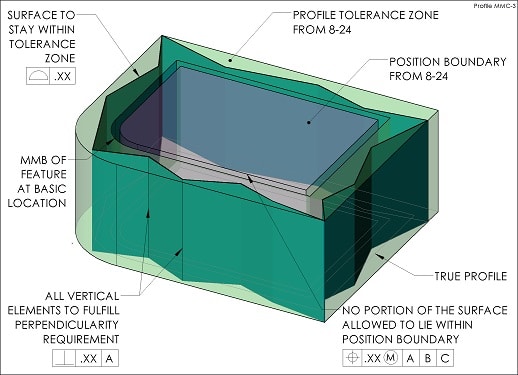
Here is Figure 8-24 from Y14.5-2009, with an additional position tolerance added:

Fig_8-24_with_Boundary_Orientation_e9erl2.png


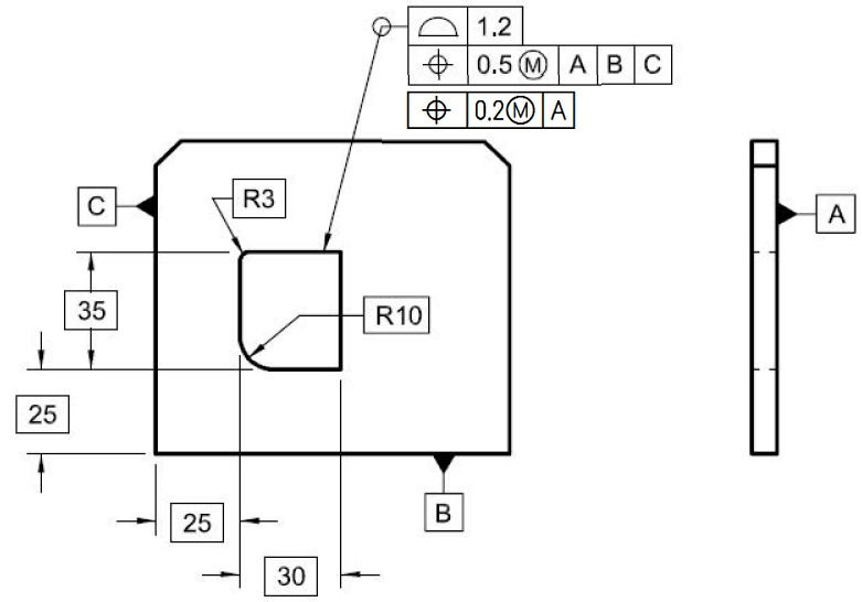
The additional callout refines the relationship of the feature to Datum A.

Is this a valid application? ;^)

Evan Janeshewski

Axymetrix Quality Engineering Inc.
 
Replies continue below

Recommended for you

Evan,
This question boils down to the perenial dillemma: is it okay to use position callout when the only geometrical characterstic to control is orientation?

If we say it is okay, then there is nothing wrong with the callout.

If we say it is not okay, then the callout should be changed to perpendicularity.

There would be no dillemma if there were two or more features like this. In that case the position to A would undoubtedly be valid calout as it would also control spacing between the features.
 
pmarc,

I agree with all that. The meaning of the callout is clear, but whether or not it is "legal" by Y14.5 is debatable. Using position to orient a feature is questionable, but applying perpendicularity to an irregular feature of size would be going out on a limb as well - there is no mention of this in Section 6.

Evan Janeshewski

Axymetrix Quality Engineering Inc.
 
I don't like position being used when it doesn't control, well... position. I interpret the definition of position as involving location, and location involves a distance. Many GD&T symbols can be control multiple qualities, but never at the price of losing their own, main definition.
It's true that the standard doesn't offer a solution to this dilemma. But rather than allowing position to do only orientation, they should simply mention perpendicularity as a sidebar to the explanation about the boundary concept (or add another paragraph to the perp section to allow this). With the boundary idea in place, the picture given in the OP would be perfectly fine.

John-Paul Belanger
Certified Sr. GD&T Professional
Geometric Learning Systems
 
Interesting...
If you read carefully thru 6.4.2, orientation tolerance zone is clearly NOT defined for complex shapes.
The work around could be to use Profile the way similar to 8-23, or Perpendicularity of "each element" the way similar to 8-25.
I would be leaning towards Profile.

"For every expert there is an equal and opposite expert"
Arthur C. Clarke Profiles of the future

 
CH -- profile's main job in life is a form control. Yet the OP graphic clearly wants the form liberated to 1.2. So I wouldn't go that route.
I do kind of like your idea of perp with each element. The only hitch is that each element is a surface control and here they want to use MMC. Shrug.

John-Paul Belanger
Certified Sr. GD&T Professional
Geometric Learning Systems
 
Well, it all starts with half-baked attempt to combine profile with MMC, right?

"For every expert there is an equal and opposite expert"
Arthur C. Clarke Profiles of the future

 
You can always write a note to describe what you want. I would be very interested to see how that note would be worded.
 
CH,

I assume by your statement that you're not a big fan of combined controls using profile and position (or other controls) at MMC? Even though its supported in the standard have you seen a lot of issues when applying it in real world applications/gauging etc..? I am genuinely asking because everything here except the question of using position to only control orientation seems kosher.
 
@chez:
It's not a matter of "fandom".
It is said in every textbook that MMC/LMC modifiers do not apply to profile, there is no virtual condition and functional gauge cannot be used.
Then, for those who still want to have it their way, Para 8.8 and fig. 8-24 offer work-around even with the picture of functional gauge.
So, when Belanger expressed his discomfort with the idea of surface control being used with MMC, I couldn't help but notice that the rules were already stretched.
Not to mention that perpendicularity of each element would refine profile, not the position; and position at MMC is still boundary control, not the axis control to begin with.

"For every expert there is an equal and opposite expert"
Arthur C. Clarke Profiles of the future

 
I'm sorry if this is not exactly on the subject the OP wanted to discuss, but i'd like to ask something about the original fig. 8-24 (without Evan's addition of the last segment in the FCF).

If the same complex feature was defined only with profile of a surface tolerance, referencing the datums and disposed unequally: [PROFILE][1.45 (U) 0.85][A][C] , single segment FCF without the position. Would the meaning be the same? Could the same functional gage be used for the boundary?
 
CH,

When you say "the rules were already stretched" you mean the as written rules in the Y14.5 standard right? As in you are saying the MMC boundary concept with profile is sort of a sanctioned bending of the rules (sanctioned because its shown clearly in an example in the Y14.5 text) and I guess should be avoided if possible? Because the only difference between Evan's example and the Y14.5 standard is the addition of another position tolerance with a single datum reference A.

I ask because this topic seems to come up a lot - people want to control irregular features of size the same way as regular features of size, with MMC.
 
I am saying, if the standard is suggesting Fig. 8-24 as the "way to go", then there is nothing wrong about adding perpendicularity requirement.
It does not contradict the other ones:
Profile_MMC_kurejv.jpg

But semiond is also asking legitimate question: do we always have to specify several controls? If position and perpendicularity can be satisfied, then "too loose" profile spec probably has no benefits and the whole thing can be simplified.
(Although, we still cannot check profile with functional gauge :))

"For every expert there is an equal and opposite expert"
Arthur C. Clarke Profiles of the future
 
CH,
I see where you're coming from - as long as that satisfies the functional requirements for the part/feature then thats fine as it accomplishes something similar, but not the same as MSS position with MMC.

semiond,
I'm a little confused with your numbers but I think you mean [0.6 (U) 0.85]Sorry you're numbers were fine! This would result in the same virtual condition but to your question (1) it would NOT be the same as the entire profile could vary between these bounds - essentially the size of the tolerance zone is 1.45 now instead of 1.2, the original control only let that 1.2 boundary float with some additional profile tolerance and (2) as CH stated, it cannot be checked with a functional gauge anymore because MMC cannot be applied to a profile tolerance.

That being said - the more I look at this the stranger it looks and the less clear it seems to me. I assume that from the way its shown in the standard that the feature is limited at its LMC size by a fixed profile boundary basically dimensioned to the datums and at MMC size it can float around the "positional boundary" shown in 8-24. However I don't think its clear what happens when all or part of the feature is between MMC and LMC - it seems to me the profile could float around the positional boundary in such a way that local deviations outside the original intended 1.2 width profile zone are allowed without actually violating the outer boundary set by the LMC size. The only way this could be fixed is if the LMC boundary follows the MMC boundary when moving around this positional boundary, but thats not the way its shown in the standard. I might be thinking too much into this but it seems unclear to me.

Edit: Sorry semiond - had a brain fart, you're numbers were fine!
 
Chez311, i understand what you are saying about the 1.2 total tolerance zone vs. the 1.45 tolerance zones in my scenario.

And now i think i even may be able to clear up some of the confusion you expressed:
The profile tolerance within 1.2 is only related to the basic dimensions of 30, 35 R10,R3 - not to the dimensions given from the datums. It builds a 1.2 wide "frame" all around that true profile where the entire surface must fit, but that frame can move in all directions because the profile segment of the composite FCF doesn't call out any datums. To constrain the location of that 1.2 wide tolerance zone, the second segment of position comes into play. It creates an internal positional boundary that takes into account:
1. the locating basic dimensions (25 & 25). 2. the profile tolerance zone width (half of it actually).
3. It's own tolerance zone (0.5, also one half - 0.25).
The above 1, 2 and 3 are being translated into a fully defined "size" and location of that boundary in relation to the datum reference frame.

Hope it might help.
 
Here is one way how a gage might be used to inspect profile:
Consider a simple case - a hole of basic size 5 is defined with 0.2 profile tolerance. An expanding pin gage is used. Let's say it was able to expand till 4.95 until it was blocked by the hole's surface. That means we have another 0.15 tolerance zone to be used (edit - for the diameter, which means 0.075 radially). Now we put the part for inspection on the optical comperator with the pin in the hole, and check that the portions of the hole surface that depart from the pin are at a distance less than 0.15-edit-correction:0.075. from the pin.
That was just a simple example offhand.
Where does the convention that gages can't be used for profile come from? Textbooks?
 
You can use gauges to control profile.
It's just since LMC/MMC modifiers do not apply to profile, you cannot rely on "functional" gauges taking advantage of "bonus tolerance" when checking fit between two parts.
Para 8.8 and Fig. 8-24 are exactly dedicated to create workaround, the way to check profile same (or rather similar) way you check position.

"For every expert there is an equal and opposite expert"
Arthur C. Clarke Profiles of the future

 
semiond,
CH got to the answer before me - note in my response I did include the phrase "functional" gauge.

In relation to my confusion on the profile/position interrelationship, thanks for your response after reading it and then looking back at the figure today it became immediately clear to me - I can be real thick headed sometimes. I didn't take notice of the fact that the profile tolerance did not have any datums applied so of course its allowed to float and shift freely around the boundary created by the position tolerance. I apologize for such a simplistic question, I should have thought about it a little harder before posing it.
 
Chez311, you sound like your being too hard on yourself. We're dealing with a field where it's very easy to get confused/lost. Especially since most of us probably do this for enrichment purposes, and we don't have the time to concentrate on details like we do with the projects at work.

CH/Chez311 this is probably my misunderstanding. I guess that i'm not dealing with GD&T "by the rules" for long enough to be familier enough with the terms and knowing the difference between a "functional gage" and simply a "gage" (i suppese that an RFS gage is not referred to as "functional"?)
 
Status
Not open for further replies.

Part and Inventory Search

Sponsor