Continue to Site

Eng-Tips is the largest engineering community on the Internet

Intelligent Work Forums for Engineering Professionals

  • Congratulations cowski on being selected by the Eng-Tips community for having the most helpful posts in the forums last week. Way to Go!

Wind farm step-up transformers - excessive gas problem 8

Status
Not open for further replies.

ters

Electrical
Nov 24, 2004
247

Please ignore my post just below this one, it is a duplicate - accidently pressed submit before finishing Subject line.

A small wind farm of five units connects to a 44kV utility line. The facility is operating for about 1 year and experiences high level of gasses at turbine step up transformers 34.5kV/690V. Turbines are 2.2MW operate at 690V, step up transformers are 2.5MVA, while the main 44/34.5kV transformer is 11MVA.

Here is a long list of fact and things which were measured, analyzed or tried:

Gassing only occurs at all 2.5MVA units while the main 11MVA transformer is fine.

2.5MVA transformers are connected to full power converters, AC-DC-AC.

The oil gas analysis (done a number of times) indicates an increased level of hydrogen, ethane, methane and acetylene, which suggests presence of partial discharge but it is unclear what may be causing it. Content of gasses increases over time ad similar rate.

The entire 34.kV collector, which is a total ~20km long is undeground cable. There is also several km of 44kV cable before the facility connects to the utility OH line.

Gas level is unrelated to the collector topology and geography – there are two 2.5 transformers close to the main substation, and one shows a much higher (2 times) level of gas than the other, and the same applies for other two units which are >10km from the sub.

Total harmonic distortion is measured and found to be in the range of 2-3% at full load, which should not be causing gassing as the full load on a wind farm rarely occurs. Harmonic content is much higher at low load but that should not matter much in terms of gassing.

The owner ordered a replacement transformer which was made a bit larger, 2.6MVA and for significantly higher V/Hz ratio then the original ones, but after several months in operation that transformer developed the same problem. The harmonic factor for this transformer remained 1, as it was for the original unit.

Various P-Q analyzers were used to measure V, I, P, Q and TDH over a longer period of time and capture events, but nothing particularly significant was captured.

Except it was identified that when utility is switching a large 30MVA capacitor bank some 30km away on the same feeder, an overvoltage spike in the range of 150% and lasting about half cycle reaches the 2.5MVA transformers, but the capacitor is being switched relatively infrequently, the average is probably less than one per day.

Turbine converter reactive capability is higher than transformer rating (2.7MVA vs 2.5MVA) and under certain operating conditions units may operate with a low power factor, but transformer apparent power still very rarely exceeds 2.5MVA and may only occur for a short period of time when only one or two units are operating at low kW output. In which cased they will be ordered by an automatic controller to import a larger amount of VARs from the grid (the facility operates at fixed power factor mode).

Various sources indicate that many wind facilities experience somewhat increased level of transformer gassing, but that this phenomena is still poorly understood and science is still to explain it. There are various hypotheses why this is occurring and mine would be that this problem may have something to do with the fact that wind turbines are the most unstable generators by far in terms of power output and event not that many loads are as unstable. They are not as bad as arc furnaces but have a lot of similarities except changes are slower.

However, transformer gassing at this facility has already reached very alarming levels, and there must be something else in addition to that phenomena which affects many other facilties. But we seem to be running out of ideas what to try next. Any comments would be greatly welcomed!

Than you for your time to read this long story :).
 
Replies continue below

Recommended for you

TR OIL SAMPLE TEST - PPM

Hydrogen (H2) - 2400
Methane (CH4) - 1800
Ethylene (C2H4) - 20
Ethane (C2H6) - 1130
Acetylene (C2H2) - 5
Propane (C3H8) - 50
Oxygen + Argon (02 + A) - 4230
Nitrogen (N2) - 19500
Carbon Monoxide (CO) - 160
Carbon Dioxide (CO2) - 1300
 
Hello, Ters.

Where are these measurements being taken? At he 690v secondary of each trafo or at the 33kV level via PTs? I would imagine that at the 690V level the distortion would be much greater than at the 33Kv level inasmuch due to the high capacitance of the long 33KV system cables, which would tend to dampen the HF components.

At the 690V windings it may be a similar situation caused by VFDs causing a lot of HF spikes of high amplitude eventually causing insulation failures in motor windings not designed for use with VFDs. The difference being that the motor windings operate in air, with no measurements of deterioration, until failure.

In the case of oil insulated transformers, the deterioration is measureable/evident by the oil tests being done, long before actual failure occurs. Basically (as I understand it) (not a VFD expert) the AC-DC/AC converter is a form of VFD.

Just some ideas.

rasevskii
 
Hi rasevskii, nice to hear from you and thank you for the reply. The measurements were taken at all voltage levels so far, 690V, 34.5kV and 44kV.

Specific THD data refers to measurements taken at 690V. At very low turbine output, like 10%, the THD may reach over 30%, but then near the full load it drops down to about 2% for voltage and a bit more for current.

I did think of converter induced spikes which are in the range of microsecond and with nono-sec raise time domain, but then there are two factors against this thinking:

1. How likely is that such short spikes, even if there are many of them in each half cycle (and we will be confirming that with an oscilloscope soon), are to pass through the low side winding and find its path somewhere else discharging through the oil as their magnitude is still low even if they reach twice the normal crest voltage at 690V RMS.

2. Turbines and converters come from a reputable manufacturer which supplies thousands of such units,so if there is something wrong in this case at 690V side, then it is some sort of mismatch between the transformer design and converter design which may not exist in other cases as pad mounted transformers come from different supplier.
 
And forgot to mention, yes the full wind converters (used in this case) are very similar to VFDs just the energy flows the other way. Actually, I'm also working on a small hydro job where a PMG generator is to be used, and offered converter is more or less standard GE medium voltage VFD.

"Full" means that the converter fully separates the grid and the generator. But many wind turbines are still supplied with partial conversion, specifically they use asynchronous doubly feed machines, with only rotor attached to an AC-DC-AC converter while the stator is directly on the grid.
 
what are the HV-LV vector groups of the transformers?

"Throughout space there is energy. Is this energy static or kinetic! If static our hopes are in vain; if kinetic — and this we know it is, for certain — then it is a mere question of time when men will succeed in attaching their machinery to the very wheelwork of nature". – Nikola Tesla
 
Both transformers (44/34.5kV and 34.5kV/690V) have DELTA on high side and directly grounded WYE on low side, and the vector grop is -30DEG, being Dy1.
 
Does the transformer have an internal switch and or fuse? The switch contacts or fuse clips could be weakened by the varying loading on the xfmr. A winding resistance test would help, but making good connections to the HV side with (an assumed) dead front connection can be tricky. The winding resistance test could help to identify any problems in the above mentioned and also the OLTC.
 
Smallgreek, thank you very much for this. We hypothesized about many things, but this was not one of them. The 2.5MVA transformer has internal fuses, actually two of them in series - one is ELSP and the other is called "weak link". So maybe the weak link is too weak :)?

What is against this hypothesis is that most transformers developed the problem after being just few months in operation, not years.

But what goes along this theory is that even though all 2.5MVA transformers produce high level of gasses, some produce twice the much then others and there in no any logic in it in terms of being unrelated to collector length or anything else we could think of. So maybe it is related to how much fuse clips are loose?

As I indicated above, a replacement transformer was ordered from the same shop, just slightly up-rated, but it probably uses the same fuses and clips. However, that transformer started developing the same problem shortly after (few months).

The replacement transformer was used to replace the unit which had the higher level of gas at that time. Then the transformers manufacturer took the original transformer back to shop and completely dismantled it for inspection, but they then reported that they could not find anything wrong with it, nor any signs or internal arcing or similar were visible.
 
And yes, transformers use dead front elbow connection, acutally two of them - there is an internal 34.5kV bus with 2 sets od cone bushings to allow "daisy chain" to the next turbine.
 
Full power inverters produce lots of high-frequency components. These are in the kHz - MHz range and are known to produce PD and Ozone. Is that something you have looked into?

It is not common to have PD in submersed parts, but it is not impossible. Are there parts that are not fully submersed? Have you inspected them for traces of possible PD?

FYI: THD or other harmonics measurement do not reveal HF components. You need to measure with a high-badwidth scope and corresponding voltage dividers or differential probes. You can use (fused) probes and a differential probe on the 690 V side. That is where the HF is best seen.

Gunnar Englund
--------------------------------------
Half full - Half empty? I don't mind. It's what in it that counts.
 
Thank you for the link rterickson. This problem may be along the same lines mentioned in the article, that one should stay away from ordinary distribution transformers for wind applications, and those are not specially designed for any particular wind induced problems, such as frequent thermal cycling, harmonics, voltage fluctuations, etc. But still we don’t have any proof yet what exactly is wrong on those particular transformers.

Gunnar, thank you for your comments. we are going to use a good 100MHz of higher frequency scope to zoom into half cycle and see what sort of kHz MHz converter spike we see. The reason why we are not rushing with it is that we are not sure what to do with that info yet and what a good reference to measure the converter noise may be:

The turbines and converter come from a reputable manufacturer and this particular WTG model is not new on the market. It has been around for several years and many of these were supplied and use the same 34.5kV collector. However, there are no reports that other facilities utilizing the same WTG experience the same gassing problem.

With this in mind, it seems to be less likely that we have good transformers but bad converters. We also don’t have a reference what a “good” converter is. All converters are noisy and will produce HF spikes. But how much is too much, we don’t know yet. And the answer to this question may not be dependent on a particular converter design, but also on kW load, which is anything but steady.

Amount and amplitude kHz and MHz spikes may not necessarily be directly related to THD%, however since current THD is about 10 times higher at 10% load vs 80% load, I would still think that distribution of high frequency components will similarly depend on the load to some extent.

Re your questions about parts not fully submersed, I don’t know that yet – don’t have full info on the transformer internal design. There are two fuses inside, they are serviceable, but I don’t know if they are fully submersed. Nor I have seen the transformer which was dismantled for the inspection - it was only reported that the manufacturer issued a statement that they could not find any traces of PD or arcing.
 
The DGA result given is taken after after how many months of initial charging or oil vaccum filtering? To me it is not a case of PD or issues from overheating from harmonic currents. H2 values and Co & co2 values rule out such a scenario.It looks like an overheated joint some where ( lead joints, tap changer contacts or fuse contacts) some where in oil. The comparatively low O2 content proves that. The overheating joint is consuming oxygen! A careful examination of all parts under oil is required. Please share with us when you finally locate the fault point.
 
prc, thank you for the reply. Could you explain how an overheated joint is consuming oxygen - what chemical process takes place there?

Re DGA numbers I posted above, the test took place some 8 months after the facility was placed in service. However, an icreased level of gas was showing at the very first DGA test done just several weeks after units were commissioned.

The above results are for one of the transformers with higher content of H2 and CH4. Here are results from another two transformers which have significantly lower content of H2 and CH4. For comparison purposes I pasted results for the one with the high content at the bottom. DGA tests were done at the same time on all 3.

Hydrogen (H2) - 700
Methane (CH4) - 870
Ethylene (C2H4) - 15
Ethane (C2H6) - 600
Acetylene (C2H2) - 3
Propane (C3H8) - 2
Oxygen + Argon (02 + A) - 8000
Nitrogen (N2) - 36800
Carbon Monoxide (CO) - 100
Carbon Dioxide (CO2) – 1100
*
Hydrogen (H2) - 1300
Methane (CH4) - 1000
Ethylene (C2H4) - 15
Ethane (C2H6) - 600
Acetylene (C2H2) - 6
Propane (C3H8) - 50
Oxygen + Argon (02 + A) - 6800
Nitrogen (N2) - 23200
Carbon Monoxide (CO) - 70
Carbon Dioxide (CO2) - 1000
*
Hydrogen (H2) - 2400
Methane (CH4) - 1800
Ethylene (C2H4) - 20
Ethane (C2H6) - 1130
Acetylene (C2H2) - 5
Propane (C3H8) - 50
Oxygen + Argon (02 + A) - 4230
Nitrogen (N2) - 19500
Carbon Monoxide (CO) - 160
Carbon Dioxide (CO2) - 1300
*
 
Ters, air contains O2 and N2 in the ratio 1:4.But the solubility of O2 in oil is almost double of N2. Hence in a free breathing( trust these are free breathing type and not sealed type) the ratio tends to become 1:2.But when there is a coking contact in oil( contact getting heated up due to carbon formation)dissolved O2 gets consumed and O2 content comes down.I have noticed the ratio going even up to 1:10 or even 1:20 in transformers with atmoseal, but with severely coked tap changer contacts in mail oil.In your case the ratio is almost 1:4. I doubt there must be a generic defect somewhere which cause heating of contact joint with out involving paper.
 
Pad_Mounted_Transformer.jpg


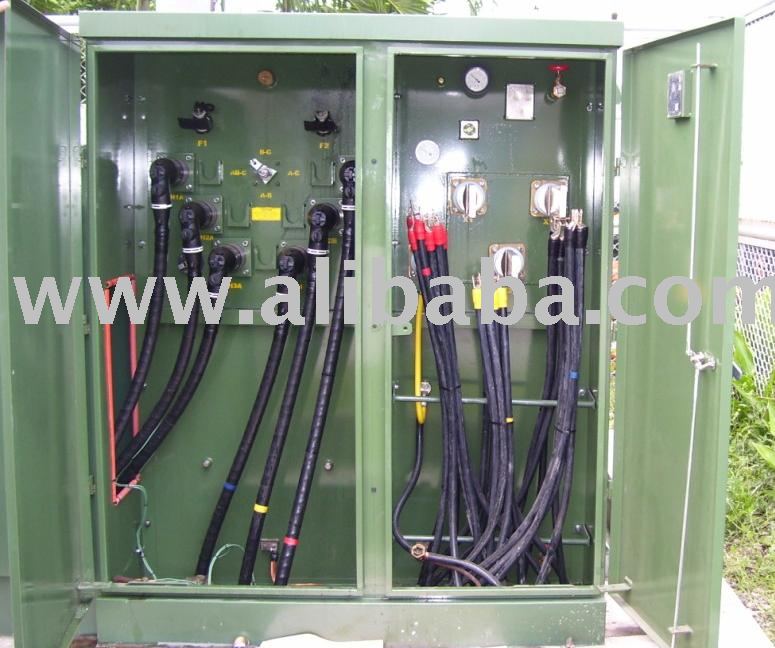
For clarity, this is what one of these units likely looks like. N2 blanket sealed. Not easy to connect to for testing (the left side utilizes "dead front" cable connectors, not easy to work on. Some units do have access panels available to get inside. Notice on the left, the 2 fuses (F1/F2) as well as the feed through(loop connection) for the HV cables. The OP also mentioned that his unit has internal switches and an OLTC (not pictured in this photo)
 
Fellows, I would like to post a follow up on this. I came across a presentation done by a reputable engineer, IEEE Fellow and member of IEEE's Transformer Committee , etc, which unfortunately I cannot publish here due to that thing: “all rights reserved” , but in essence the conclusion is:

Most 35kV wind pad mounted transformers are with 5-leg wound cores and most produce gas not due to dielectric breakdowns on windings of any kind but gassing comes from the core due high inter-laminar capacitance allowing for high capacitive charge. The solution would be either inside (not outside) core grounds or core shield. The presentation underlines that using outside core grounds results in high core volts, while inside core grounds eliminate static charges and reduce core volts to volt/turn level.

The other conclusion is that this gassing phenomena appear to be directly proportional to the operating voltage, meaning that wind transformers operating at voltage lower than 35kV see much less of this problem (and hence, I suppose, those working at higher level, such as 46kV, and there are some of those as well, may see even more).

This all may very well be the case, an in essence it sort of suggests that high ratio and relatively high voltage transformers are prone to this gassing problem. But that is a bit debatable, maybe they still are behaving so if attached to a wind turbine (and if so it, it is to be explained why), but there are 35kV transformers stepping down to several hundred volts for some industrial applications and I could not find any references suggesting that these have gassing problems as well.

Any comments?
 
I don't work in wind operations but I've heard of this problem before. A crew from a oil processing contractor we use said they just spent several months degassing over 150 xfmrs at a large wind farm in the midwest. Have you reached out to any other wind operators to see if they know what's going on?
 
Have you reached out to any other wind operators to see if they have the same problem? A crew from a oil processing contactor we use said they just spent several months degassing over 200 xfmrs on a wind farm in the midwest....
 
Status
Not open for further replies.

Part and Inventory Search

Sponsor