Continue to Site

Eng-Tips is the largest engineering community on the Internet

Intelligent Work Forums for Engineering Professionals

  • Congratulations cowski on being selected by the Eng-Tips community for having the most helpful posts in the forums last week. Way to Go!

Welded Shear Tab

Status
Not open for further replies.

Cal001

Structural
May 29, 2020
2
Hello
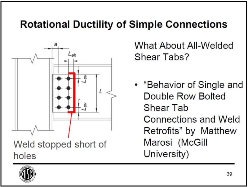
I am just curious and want to get your input into the following connection where the shear tab is welded all around with the beam web.
1) Is it allowed by the code
2) Are there any fabrication issues with shop welding
3) For design of this weld configuration i.e for shear capacity of weld all around (with Vertical shear and axial tension) can we use Table 8-6 AISC 13th edition, or would it be safe bet to consider C- shaped weld and use table 8-8
4) How about the check for the beam web (base metal check. Can we assume the beam web with weld all around.

 
Replies continue below

Recommended for you

Can you post a sketch of the condition? I've never seen a shear tab that can get a true "weld all around." Do you mean welding the vertical and horizontal interfaces to the face of the web on one side and the vertical to the end of the web on the other?

What code are you using? You mention AISC SCM 13th edition, so I'm guessing...IBC 2009 or a local code derived from it?
I wouldn't say that's not allowed, but it may not be a "shear tab" anymore. How is it being attached to the column? If it's a plate welded to the column, it's definitely not a shear tab. If it's a single angle bolted to the column, you may be able to get away with it. "Shear tabs" are detailed such that, at ultimate load, they undergo a reliable deformation (driven largely by "plowing" of the bolts in the bolt holes) to allow the beam ends to rotate enough to make your pin-pin model plausible. If you've got all welds, your connection will be more rigid at ultimate loads than the prescriptive shear tabs and, as such, you'd need to modify your model to account for that additional fixity to accurately predict how the structure will behave. As long as you've accounted for the actual structural response, sure - you're allowed to do it.

All the typical weld group and base metal checks would still apply.
 
Hi all,

I agree with phamENG, an all welded shear tab doesn't seem to have enough rotational flexibility and ductility to accommodate the end rotations of a simple supported beam as required by the AISC Specification Section J1.2.

In extended shear tab connections, the geometry and thickness of the plate are configured so that the plate will yield, bolt group will rotate (e.g. using short slotted holes), and/or the bolt holes will deform to provide rotation capacity. The first approach (plate yielding) may be suitable for a welded shear tab if detailed and designed properly. Larry Muir, in an AISC webinar called "Alternate Methods of Connection Design", provide some insights on this subject. You can find the recorded webinar in the fallowing link.


However, I would go for a bolted shear tab unless it is for a retrofit or to fix a construction problem.

All_welded_extended_shear_tab_pqhxoj.jpg
 
Hello

PhamEng you got it right it is welded all around. It tried attaching the link of sketch with this post but somehow did not got attached.

Thank you PROYECTOR for sharing the webinar.

Unfortunately we are stuck with welded modules as these are being shipped from Asia to North America.So to avoid huge marine forces and risk of bolted connections rocking. It was decided to have welded connections
 
 https://files.engineering.com/getfile.aspx?folder=f4272820-22d1-42c8-95b3-db20970640c4&file=IMG_5588.jpg
So getting back to the question. "1) Is it allowed by the code"

It might be hard to neatly shoe horn this connection easily into your relevant code. This seems to display most of the characteristics of a 'rigid connection' though it likely doesn't meet the minimum strength requirements. If you have modeled this connection as a flexible connection then your connection doesn't meet the match your model.

Unfortunately we are stuck with welded modules as these are being shipped from Asia to North America.So to avoid huge marine forces and risk of bolted connections rocking. It was decided to have welded connections

That alone doesn't seem to explain why you need full weldments of this nature.
 
I don't see problem with the web weld, as there is a stiffener on the opposite side. The connection can take a lot of abuse before fall apart. I don't have access to the tables, so no comment there.

As the connection can be seen as semi-rigid, in reality, it will draw moment. So it is essential to double check the beam web that can provide adequate resistance without damage.
 
Cal001 - for future reference, that's an inappropriate use of the "weld all around" symbol.

You need to dig into partially restrained moment connections - they live the nebulous space between pin connections and fixed connections. While I'll grant you that all connections actually live in this space, these are far enough from either that it really matters. I would guess that, under service loads, your beam is not going be able to rotate more than the torsional rotation of the girder. Ad you approach ultimate load, I imagine it will start to rotate some but likely not enough to qualify as a pin and you'll see you a non-ductile failure before the strength of a fully restrained connection.
 
If stability is only a concern during transportation, diagonals can be place around corners to prevent distortion. Bolt connection is more desirable than weld two plates together.
 
Status
Not open for further replies.

Part and Inventory Search

Sponsor