Continue to Site

Eng-Tips is the largest engineering community on the Internet

Intelligent Work Forums for Engineering Professionals

  • Congratulations cowski on being selected by the Eng-Tips community for having the most helpful posts in the forums last week. Way to Go!

True Profile Definition

Status
Not open for further replies.

pmarc

Mechanical
Sep 2, 2008
3,227
Hello,

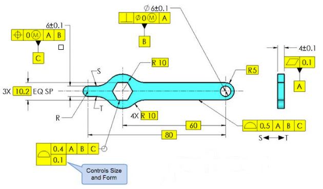
Below is a snapshot taken from the most recent Tec-Ease tip available on their website. My question would be following: Does anyone think that the true profile between points S and T (clockwise) has not been fully defined? I am specifically thinking about close vicinity of points S and T. Thank you!
capture_bjnd61.jpg
 
Replies continue below

Recommended for you

Here is my take on Evan's last example:
Considering basic radius R30:
MMC=29.95, in that condition it can translate right by 0.3, resulting in VC boundary of 29.65.
LMC=30.05, in that condition it can translste left by 0.3, resulting in RC condition of 30.35.
If i was to translate it to composite profile: 30.35-29.65=0.7 - in the top segment, 0.1 in the bottom segment. That means that one of pmarc's proposed solutions is what i would go with.

Edit: the above calculation is in consideration of the boundary interpretation, in accordance to Evan's intent. If i was to analyze by the axis interpretation (which i prefer) the results would be different in this case.
 
semiond,
I fully understood that you used the radius gage example just as a illustration of the concept of AME.

I am just not sure that you understood what I was trying say in my example with three inspectors. If three different inspectors can get three different maximum inscribed circles (regardless of inspection method and equipment) and there is no objective way to decide which of them is right, this, among other things, means that the concept of maximum inscribed circle/cylinder (AME, UAME) does not sit well for partial arcs. It is that simple and I am afraid I cannot make it any clearer.
 
pmarc said:
semiond,
To your question, the problem with the use of radius gage is that there are multiple solutions of this measurement task.

If the problem is not with the radius gage, but as you say now - with the concept of finding an inscribed arc regardless of inspection equipment, then i must say that according to my experience, if the inspected arc looks like the one in aniiben's example, the three inspectors you mentiones would not have much trouble finding an inscribed arc and determining the location of it's center. Several times I had the opportunity to measure something similar myself, much smaller arc length in fact, and the curvature was more or less proportional to aniiben's sketch. One time i remember clearly, after a customer complaint on a part i was designing, the manufacturing guys made a correction to the production process. We had the center location results rechecked by different people and the differences were always less than 0.01mm. After that correction, the custmer was satisfied with all subsequent orders.
 
Hi All,

I would say that the two position tolerances in my last example are equivalent to a profile tolerance of 0.4 to A|B|C. This is consistent with the offsets shown in the Combined Controls example in Fig. 8-24.

I would also maintain that these position tolerances fundamentally control the surface relative to a boundary, and I have an easier time defining it that way. Any properties relating to diameters, radii, mating envelopes, and axis geometry are purely coincidental, and only occur in the special case of the true profile being an arc-shaped surface (a segment of a cylinder). If the true profile was some kind of curved surface that was not perfectly arc-shaped, with no definable radius or axis, then the tolerance could still be defined. But we need to have definitions that are based purely on the surface and boundary offsets.

Evan Janeshewski

Axymetrix Quality Engineering Inc.
 
semiond,
According to my experience this kind of measurement is highly unrepeatable, and even if repeatability is achievied there is no certainty that the calibrated value is trully the radius of maximum inscribed circle.

So where is the truth? Please don't answer. I think we have said enough in this thread to be able to realize that we will not find agreement here ;-)
 
Evan,
I think you treated your 2 unilateral boundary 0.3 position tolerance zones as if it was one bilateral 0.3 tolerance zone.

Location + form within 0.4 in reference to the datums, is only 0.2 to each side from the true profile. That is while each position tolerance alone allows translation of 0.3 to it's respective direction.

Fig 8-24 is different, because the boundary there is all around the closed surface and the 0.5 position tolerance is resulted in a boundary at distance of 0.25 from the MMB contour. In case that the surface is not colsed and each position tolerance works to limit translation in only one direction, (edit: there us no reason) to divide each 0.3 tol. zone by 2.
 
Pmarc, that's fair enough. We agree to keep disagreeing on this matter. I must say though that i'm fully aware that your position is the one commonly acceptable. I choose to stay in the low minority in regard to that.
 
semiond,

I agree that the boundaries are only 0.2 to each side of the true profile. I don't agree that each position zone allows translation of 0.3.

The standard doesn't cover the case of a position applied to an "open" surface, so we are both guessing at what would happen if they did. But it would be very inconsistent to make the boundary offset by half the tolerance value for closed surfaces, and the entire tolerance value for open surfaces. I would say that there is no reason to do this.

Part of the problem (perhaps a large part) is that we have a tolerance type (position at MMC) that was originally defined in the context of regular features of size (cylinders, widths, spheres) and was then extended to apply to other features. The surface interpretation of the position of an internal regular feature of size at MMC defines a virtual condition boundary that is the MMC size minus the position tolerance. Simple. But then we try to apply position at MMC to an "irregular feature of size" that defies simple numerical description (does not have directly opposed surfaces, a size tolerance, an MMC size, or even a definable size characteristic). Not so simple. The "virtual condition is the MMC size minus the position tolerance" concept for reqular features of size gets generalized as the "positional boundary is the MMB at basic location offset by half the position tolerance" for irregular features of size. This is what we see in Figure 8-24.

Evan Janeshewski

Axymetrix Quality Engineering Inc.
 
Evan,
We seem to agree that since this is the kind of application not covered by the standard (but not explicitly forbidden), there is no completely solid and unquestionable basis to interpret the "virtual condition is the MMC size minus the position tolerance" in a way that will always reject the assumption that the whole 0.3 tolerance zone can be used for a deviation from the MMC boundary. I can easily see disagreements between suppliers and customers arising due to this duality, or designers tightening tolerances beyond what's needed "just in case".

This is also part of my position that the axis interpretation, although it comes with the discomfort of the need to establish UAME, is more consistent in cases such as this. It would arise no questions regarding how much of the cylindrical tolerance zone for the axis is usable. I say "discomfort" and not "illegality", because there seems to be no direct or implied statement in the 2009 standard that partial arcs have no AME, or that they are not features of size. If there was, i think we couldn't use the position tolerance in the first place.

I would add a note that would require the manufacturer to work by the axis interpretation.

 
pmarc said:
I would really like to avoid adding another side topic to the discussion, but the (sad) fact is that even for a simple arc like you showed, the standard does not really offer any interpretation of what the actual size of the arc really is. The surface of the arc must lie inside a crescent-shaped tolerance zone, but inside that zone all kinds of different things can happen. The actual arc can be a a collection of multiple smooth portions with curvatures of totally different radii than defined by the drawing limits. The actual arc surface can be full of flats and/or reversals for which there might be dozens of different local radius values or for which it might not even be possible to determine any radius. And the fact that modern measuring machines operators/programmers are able to detect an axis of an arc does not mean that they do it according to the standard (it is hard to blame them if the standard is of no help here).

Pmarc,
Well, you just did (add another side topic)

And one interesting thing about the arc/ radius definition is that even if the arc is defined with profile (as probably it should for a robust product definition) we are not out of the woods yet. At least to my own opinion, belief formed based on different readings and opinions found here on eng-tips.com and on other sites.

If we take for example R 4.50 – 5.50 radius defined with ± (R5.0 ± 0.5) and convert it to profile within 1.0, along with R 5 basic then based on my CAD system I can fit a radius on R 9.53 within the tolerance zone of 1.0 mm, which is way bigger than the limits we started from. Also, with some additional patience you can fit 3.25 radius within same boundaries of 0.1 1.0mm tolerance zone.

Does anyone agree with my assessment?

Looks like a composite profile could be an even beter refinament to match the original R± callout.....
 
Greenimi, what you describe makes sense.
I think that the reason for it is the different shape of the tolerance zones, and therefore different areas:

+- tolerance zone is crescent shaped with it's corners located wherever the arc shaped feature starts/ends, be it sharp corners like in aniiben's sketch or tangent faces like in fig. 2-22 in the 2009 standard. There is no theoretical center present in the definition.

Profile tolerance on a radius results in a tolerance zone that consists of 2 concentric theoretical radii, and thus they are at a uniform distance from each other all along their length. This is why you can fit "out of tolerance" radii inside- the tolerance zone is in fact larger in area. No crescent-shape. By the way, i think that the common center of the 2 tolerance-zone-limiting-theoretical-arcs should be fixed in space for the definition to be meaningful.
 
Status
Not open for further replies.

Part and Inventory Search

Sponsor