Continue to Site

Eng-Tips is the largest engineering community on the Internet

Intelligent Work Forums for Engineering Professionals

  • Congratulations cowski on being selected by the Eng-Tips community for having the most helpful posts in the forums last week. Way to Go!

True Profile Definition

Status
Not open for further replies.

pmarc

Mechanical
Sep 2, 2008
3,227
Hello,

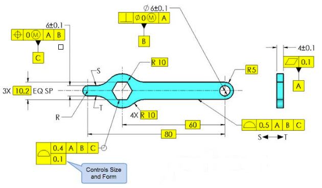
Below is a snapshot taken from the most recent Tec-Ease tip available on their website. My question would be following: Does anyone think that the true profile between points S and T (clockwise) has not been fully defined? I am specifically thinking about close vicinity of points S and T. Thank you!

capture_bjnd61.jpg
 
Replies continue below

Recommended for you

pmarc said:
The concept we are discussing here has in fact very little to do with inspection - it is all about understanding what the actual mating envelope really is and even more about what the feature of size really is.

For me, the inspection subject is only a way to visualize the physical/geometrical aspect of the theoretic concepts we are discussing.

I don't know how my interpretation of the UAME concept per the cylindrical simulator making maximum contact with the arc is in conflict with the standard. I think it sits well within the definitions.

And, can't the arc be considered an irregular feature of size?

Also, note fig. 4-29. If an arc less than 180 deg. can be used as a datum feature and it's derived axis can be an origin for measurements, why can't a similar arc be used for contact with an UAME simulator for position control? I find it a little strange.

Please note that i'm not trying to disagree for the sake of disagreement. I have to make it clear that i learn a lot from the interaction here with you and with other members and appreciate your explanations very much.
 
semiond,
We are spinning around here. If I say that the arc from aniiben's sketch is not an irregular feature of size because it is impossible to determine the actual size of the maximum cylinder inscribed in that feature, you will say it is possible and we will be back in the starting point.

Here is my another (last?) attempt. Let me ask you this: what is the maximum possible size of a cylinder unrelated to any datums that could mate with the actual as-produced arc? By "mate" I mean freely pass through the arc. Assuming that the basic radius of the arc in aniiben's sketch is 50, are you able to give me the maximum value of the diameter of that cylinder?

As for fig. 4-29, both cases shown on it are different from the scenario we are discussing here.

In fig. 4-29(a), that is where the secondary datum feature B has been referenced RMB, the datum feature B simulator expands in size from LMB (14.9) towards MMB (15.1), but it is fixed in location relative to datum axis A. This means that there has to be a point where the simulator will finally stop expanding. In aniiben's case, on the other hand, the location of the center of the UAME can be anywhere, so the gage cylinder simulating the UAME can expand in size to infinity. That is the difference here.

In fig. 4-29(b), that is where the secondary datum feature B has been referenced at MMB, the datum feature B simulator is fixed in size at 14.9. The size of the simulator is not calculated/determined from/by any actual value, it is a value calculated/determined based on the tolerance values and tolerancing scheme specified on the drawing. This is why no one has to worry in this case about the UAME of the arc and its size.
 
In figure 4-29 there is no derivation of the location of the arc centerline. The location is basic.

edit - pmarc beats me to it while I was looking up the figure.
 
semiond,
You look like a practical kind of guy.
Imagine round feature. You can grab it with chuck / collet kind of device and reliably know where the center is.
Now, as you cannot grab "open" less-than-180-deg. feature, you have to employ far less reliable methods of finding position of the center.
So, it is agreed almost universally that it is better to control outline of the edge using profile, rather than trying to find elusive center:
Capture_aibddl.png

In fig 4-29 arc is acting as secondary, "clocking" datum, it doesn't control any central axis position at all.
I don't know if it will help, but try to re-read definition of irregular FOS one more time.
Just my 2 cents.


"For every expert there is an equal and opposite expert"
Arthur C. Clarke Profiles of the future
 
semiond said:
Also, note fig. 4-29. If an arc less than 180 deg. can be used as a datum feature and it's derived axis can be an origin for measurements, why can't a similar arc be used for contact with an UAME simulator for position control? I find it a little strange.

This is a completely different scenario. You aren't deriving a center, the location of the center of the datum feature is expressly defined.

John Acosta, GDTP Senior Level
Manufacturing Engineering Tech
 
pmarc,
I hope i don't make you lose any patience, because i find this discussion effective and very interesting (it is for me), even if some points are not fully clarified or agreed upon from first attempt.

I'd like to address your question:
pmarc said:
what is the maximum possible size of a cylinder unrelated to any datums that could mate with the actual as-produced arc? By "mate" I mean freely pass through the arc. Assuming that the basic radius of the arc in aniiben's sketch is 50, are you able to give me the maximum value of the diameter of that cylinder?

To answer this question i would first need to measure the arc along it's full length and determine it's actual contour. Let's say the whole arc varies between R49.98 to R50.05 like shown in this picture (i modified it a little for the relevant values but you will probably recognize the source[wink]:
20180622_004226_riz5ob.jpg


In this case, the gage diameter edit: radius that would simulate the UAME correctly is at the size of 50.05. If the gage is any larger, it will only be supported on the edges separating the arc from it's surrounding surfaces, and will completely depart from the circular surface itself (like i described earlier - similary to a radius gage larger than the as-produced radius of an arc), and will no longer comply to the standard definition of an actual mating envelope - the general definition from para 1.3.25:
"A similar perfect feature(s) counterpart of smallest size that can be contracted about an external
feature(s) or largest size that can be expanded within an internal feature(s) so that it coincides with the surface(s)
at the highest points
.


As for fig 4-29, i was addressing illustration (a) only, and maybe it's not the best example because the center axis of the simulator is indeed fixed in location to another datum and thus the simulator itself can only vary in size but not dislocate in space.
I know the whole thing is different from what we are discussing here, but my point was - if an arc less than 180 deg is good enough to be used as a datum feature and it's axis is adressed in the design (fixed or not, it's location matters), why can't a similar arc be controlled for position in relation to other (datum) features?

To the other repliers and especially CH- thank you for your much appreciated input. I will reply to you later.
 
pmarc,

I agree that the combination of profile and position shown on the drawing does not fully control the characteristics of the feature. The drawing is incomplete - there would need to be another tolerance to control the arc surface in the minus material direction. Here is one possibility:

MMC_on_Non-Enveloping_Surface_3_hmvifu.png


Is this twice as invalid, or does the invalidity at LMC cancel out the invalidity at MMC? Or is it invalid regardless of the undefined size? ;^).

semiond,

Over the years I've learned to avoid basing anything on what words and terms are used to describe or classify a geometric tolerance. The terms are often undefined, and open to debate. Position is classified as a tolerance of location, but what are the criteria for a tolerance to locate a feature? I would agree that the position tolerance in the original drawing doesn't locate the arc surface in all possible directions, but it does locate it in "half" of the applicable directions (see above).

Evan Janeshewski

Axymetrix Quality Engineering Inc.
 
CH,
aniiben, who presented the problem, noted that it is preferred in that particular case to apply position over profile, because they want to utilize the advantage of MMC. Modern measuring machines can detect an axis of an arc-shaped feature quite repeatably, even if it doesn't contain opposed points.

If they prefer to use advanced measurement equipment in order to gain the production bonus given by MMC callout, why reject it?

As for the feature of size definitions in the standard - i find them subject to different interpretations. i would say that if interpreted solely by the text in the body of 2009 standard, para. 1.3.32.1, the arc could even be considered as a regular feature of size, despite of the common opinion that those have to contain opposed points or the "180 deg. rule". I don't see how the standard explicitly states, or implies this. It says that there must be a directly toleranced dimension. Can't the radius of an arc, that could as well be toleranced by +-, be considered a directly toleranced dimension?
(As a side note: i know that some will consider a combination of a basic radius and a profile callout, as aniiben showed, an indirect tolerancing method - but this small issue is not what was put in focus in this discussion).

Axym, perhaps i was a bit carried away in my response, because indeed the text of the standard doesn't explicitly prohibit the use of position tolerance for limitation of translation in one direction only. But it seems to me that the boundary interpretation, usually explained by a examples such as a hole that is limited in translation in all directions by a boundary created by a virtual pin at the holes' MMC condition, is intended to be applied in cases where the shape of the feature indeed contains opposed points and can be restricted by the boundary simulator. In case of a less than 180 degrees arc where such restriction in translation is impossible, i think that the boundary interpretation is less appropriate or useful. However, an axis interpretation can still be valid. With that said this is only my personal point of view, and the most important thing that should be taken into consideration is the design intent.
 
Evan,

As long as we are not saying that the axis interpretation of both position callouts in your proposal holds water, I am okay with the proposed solution (of course assuming we are taking functional requirements out of equation).

semiond,
We, that is, different forum members, have been going through many discussions about different inconsistencies in Y14.5's definitions over the years on different occasions. And I think most of us will agree that many of the definitions have issues, can be understood in multiple ways and therefore could/should be improved.

Feature of size definition (either regular or irregular) is no exception here, but I can tell you with 100% of certainty that a single partial arc (less than 180 degrees) should definitely not be considered a feature of size (if you did not have a chance already, you can try to check it out by taking GDTP Certification exam, where there is a specific question on that topic).

Similar story with the AME definition. I am not sure how will the new version of the math standard, Y14.5.1, approach to that problem, but in the version from 1994 the AME definition was inherently tied with feature of size concept. In other words, if considered feature was not a feature of size, it did not have AME. If there was no AME, there was no chance to robustly determine axis or center plane of the feature.

As for your example with fillet (I assume it is internal arc), the reason you were able to determine the maximum radius of inscribed arc is because you assumed that the arc was tangent to the adjacent faces and so it only had to get in contact with one point on the arc. This will not work in aniiben's case simply because the geometry does not contain any elements tangent to the arc.

I would really like to avoid adding another side topic to the discussion, but the (sad) fact is that even for a simple arc like you showed, the standard does not really offer any interpretation of what the actual size of the arc really is. The surface of the arc must lie inside a crescent-shaped tolerance zone, but inside that zone all kinds of different things can happen. The actual arc can be a a collection of multiple smooth portions with curvatures of totally different radii than defined by the drawing limits. The actual arc surface can be full of flats and/or reversals for which there might be dozens of different local radius values or for which it might not even be possible to determine any radius. And the fact that modern measuring machines operators/programmers are able to detect an axis of an arc does not mean that they do it according to the standard (it is hard to blame them if the standard is of no help here).

And to give you my answer to the question: "What is the maximum possible size of a cylinder unrelated to any datums that could mate (pass through) the actual as-produced arc (in aniiben's sketch)?", the answer is, there is no such maximum limit. A cylinder of diameter of 100 or 200 will also pass through the arc - it will just not go that deep inside the arc like the cylinder of diameter 50. This is possible because there is nothing on the opposite side of the arc that would stop someone from increasing the diameter of the cylinder to infinity, in theory.
 
Evan, I too am on board with the meaning of your drawing. I think you were just presenting it as an example. This appears to be the exact same thing as composite position. 0.3 in the upper segment with respect to ABC, and 0.1 in the lower, no DRF. WOuld you agree with that?

John Acosta, GDTP Senior Level
Manufacturing Engineering Tech
 
John,
Although I believe you meant composite profile, not position, this is quite interesting observation.

You said that the value to use in the upper segment was 0.3. I am not Evan, but after reading his reply from June 20th, I would assume that his answer will be 0.4 in the upper segment. 0.4 is a sum of profile tolerance value (0.1), half of position tolerance value in the direction that adds material (0.3/2 = 0.15) and half position tolerance value in the direction that removes material (0.3/2 = 0.15).

But my question would be following: if I say that the value to put in the upper segment of composite profile tolerance should be 0.7 = 0.1+0.3+0.3, where will I be making a mistake?
 
Yes, you are correct. I meant composite profile.

I don't think I agree that the value should be 0.4. The boundaries are such that they cannot be violated so the profile tolerance can't be additive to allow such a thing. This is currently in pencil (mentally speaking) as I don't have the opportunity to completely think it through right now. I will when I get home tonight though.

pmarc said:
But my question would be following: if I say that the value to put in the upper segment of composite profile tolerance should be 0.7 = 0.1+0.3+0.3, where will I be making a mistake?

I think you're making a mistake by not using only half of the allowable tolerance. Since we only have one side of a feature to consider we only consider half the tolerance. Maybe I'm not understanding what you're saying.

John Acosta, GDTP Senior Level
Manufacturing Engineering Tech
 
No, you are understanding correctly what I am trying to say. I am basically asking why in this case (the case with a non-closed contour) only half of the position tolerance zone value is used to determine the Least and Maximum Material Boundaries of the toleranced feature.

I am not saying that I am correct. I would just like to be convinced that I am incorrect.
 
Well, if the radius is basically located from the datum reference frame and the radius itself is basic (which it should be) then I don't see how a 0.7 interpretation is sound. That's fundamental. Did I add too much to the scenario to suit my needs or is that sufficient as an explanation?

John Acosta, GDTP Senior Level
Manufacturing Engineering Tech
 
This is what can be found in para. 8.8 "Combined controls":

"Profile tolerancing may be combined with positional tolerancing where it is necessary to control the boundary of a noncylindrical feature. See fig. 8-24. In this example the basic dimensions and the profile tolerance establish a tolerance zone to control shape and size of the feature. Additionally, the positional tolerance establishes a theoretical boundary shaped identically to the true profile. For an internal feature the boundary equals the MMC size of the profile minus the position tolerance, and the entire surface must lie outside of the boundary [...]"

Knowing this, why couldn't I say that 0.3, and not 0.15, should be subtracted from the MMC size of the profile and added to the LMC size of the profile to establish LMB and MMB of the contour?
 
For the combined position/profile callout let's say the basic radius is 30mm. The diameter would be 60 You would subtract 0.1 from it to get 59.9 to obtain the MMC of the diameter (as an internal feature) then subtract 0.3 from it to get a 59.6 inner boundary that cannot be violated. This lines up with your first thought about the upper segment being 0.4 so you're right about that and I was wrong. This inner boundary is a diameter, even if the feature itself doesn't fully encompass it. The distance from the center of the basic radius to the edge of the boundary is 29.8. This follows the definition you provided. What am I not seeing?


John Acosta, GDTP Senior Level
Manufacturing Engineering Tech
 
pmarc said:
As for your example with fillet (I assume it is internal arc), the reason you were able to determine the maximum radius of inscribed arc is because you assumed that the arc was tangent to the adjacent faces and so it only had to get in contact with one point on the arc. This will not work in aniiben's case simply because the geometry does not contain any elements tangent to the arc

pmarc, my dealing with this had nothing to do with the tangent faces near the arc in the figure i used. I had aniiben's case in mind all the way. Sorry to bug you again with this matter, but i'm afraid i might have been misunderstood. Let me approach this through a question, and sorry if i repeat myself - do you think you could use a radius gage , the way this simple and basic device is intended to be used for internal radius size verification, on the arc in aniiben's example? If the answer is yes, that means you can find an inscribed arc of "perfect" form and largest size. If you find an inscribed arc of "perfect" form and largest size, it means you found an unrelated actual mating envelope. If you can find an actual mating envelope, you can find it's axis as well. I know i oversimplify things here a great deal and ignore some technical issues, but this is the only way i can communicate clearly my understanding of this concept right now (not my practical suggestion on how to do such a verification).

As for your answer on your own question, i think that a cylinder twice as big in size as the arc, that theoretically will not touch on the curved surface of the arc at all, but only on it's edges, has very little to do with something that can be considered as an actual mating envelope for the arc. Maybe the uncertainties of the standard allow to consider the edges of the arc (the corners where the arc ends) as part of the curved arc itself, and thus that oversized cylinder would still be taken by someone for an UAME - i don't know, but i think that this approach should be rejected by common sense.

You are obviously very experienced in this field, which i can't say about myself, and i will take your word for it that less than 180 deg arc should not be treated as a feature of size, and if this issue is addressed in the certification exams there is probably a good reason for it, but i must say that i'm pretty far from understanding what is it there that is considered so fundamentaly wrong, and why it's not directly addressed in the text of the 2009 standard. I've seen far less reliable things acknowledged as legitimate in this forum and elsewhere, than simulation of a center axis from a partial arc.
 
John,
Your argumentation is based on the conversion of basic radius to basic diameter from where you are starting to subtract tolerances. From Y14.5 point of view, why would I have to do the conversion in case of a contour containing no opposed points?

semiond,
To your question, the problem with the use of radius gage is that there are multiple solutions of this measurement task. Inspector #1 may choose a radius gage of certain size, say 50.05, and claim that this is the one that simulates the maximum inscribed circle. Inspector #2 may choose a radius gage of different size, say 50.25, and also claim that this is the one that simulates the maximum inscribed circle. Inspector #3 may have another opinion, say 50.50, etc., etc.

That is because there is no "physical objectivity" in the assessment of what the maximum inscribed circle really is in case of partial arcs. And even if the numbers I have given in this scenario are not like 50, 100, 200, the difference in chosen gages will still lead to 0.45 (50.50-50.05) of difference in locations of so called centers of the arc. That should not happen.
 
pmarc,
Like i said, a radius gage is not my suggestion for a method to do the physical inspection, it is simply my last way to describe the concept of an actual mating envelope in a case such as this. I may be wrong, but i'm not sure that my previous attempts for communicating my intent were successful (including the illustration). I say it because you were suggesting that i was somehow relying on the faces tangent to the arc in the figure i used, which are irrelevant for aniiben's case, and because you were apparently suggesting that the form of the irregularities of the as-produced radius may somehow make the UAME estimation ambiguous.

For the actual measurement, there are plenty of more reliable and advanced devices that can produce repeatable results regardless of which inspector is the unlucky one to be at the shift [smile].
Sorry for not making it clearer earlier.

Edit to get an important point across: per my understanding, the demand for the UAME simulator of an internal feature, is that it must be of the largest size that will allow it to make maximum contact with the relevant feature. Not that it can grow within it until the feature blocks it physically.

Edited for better phrasing.
 
pmarc,
Regardless of the UAME/FOS issue:
You didn't want to add another sub topic, but since it's already there, i'd like to add my 2 cents on it too [smile].

pmarc said:
I would really like to avoid adding another side topic to the discussion, but the (sad) fact is that even for a simple arc like you showed, the standard does not really offer any interpretation of what the actual size of the arc really is. The surface of the arc must lie inside a crescent-shaped tolerance zone, but inside that zone all kinds of different things can happen. The actual arc can be a a collection of multiple smooth portions with curvatures of totally different radii than defined by the drawing limits. The actual arc surface can be full of flats and/or reversals for which there might be dozens of different local radius values or for which it might not even be possible to determine any radius.

I totally agree with that. If i was to measure a radius like that, specified by "R...+-..." in the drawing, i would not know what to fill in the inspection report, if i wanted to go strictly by the standard.
I would fill in the value of the inscribed radius by the extremities (50.05 in my illustration) because this is how they do the measurement on an optical comparator at my workplace - but theoretically speaking, that is only the maximum-end limit of the as-produced tolerance zone of the radius.
However, i think that for cases where an actual fair form and determinable radius are important, the standard offers the "Controlled Radius" (CR) specification.
If i'm not missing something this is also only a partial solution, because the tolerance zone is still crescent-shaped, the produced radius within it is supposed to be this time as close as possible to perfect circular form, but nothing indicates exactly how close it should be to it.
What the standard does mention in this context is: "It is recommended that the CR be further defined with an engineering control specification."(para 2.15.2) I'm not sure what that engineering control could be, but if it is proposed to use a profile control, it requires a basic radius, which will eliminate the possibility to use the direct "CR...+-..." specification in the first place[ponder]

*Edited because of poor english
 
Status
Not open for further replies.

Part and Inventory Search

Sponsor