Continue to Site

Eng-Tips is the largest engineering community on the Internet

Intelligent Work Forums for Engineering Professionals

  • Congratulations cowski on being selected by the Eng-Tips community for having the most helpful posts in the forums last week. Way to Go!

True Profile Definition

Status
Not open for further replies.

pmarc

Mechanical
Sep 2, 2008
3,227
Hello,

Below is a snapshot taken from the most recent Tec-Ease tip available on their website. My question would be following: Does anyone think that the true profile between points S and T (clockwise) has not been fully defined? I am specifically thinking about close vicinity of points S and T. Thank you!
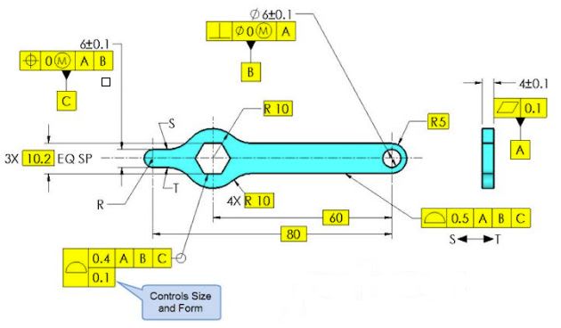
capture_bjnd61.jpg
 
Replies continue below

Recommended for you

aniiben,
Let's say that in your figure the nominal shortest distance between the edge of the arc and the edge of the hole B is 10. With the dimensioning scheme proposed, what stops the actual edge of the arc to be manufactured in a way that its edge is for example only 0.1 from the edge of the hole B?

To answer your question more directly, the toleranced feature does not have to be a closed shape, but there has to be an envelope (regular or irregular) of determinable and finite size that can be inscribed in or circumscribed on the toleranced feature. In other words, the toleranced feature must either be regular or irregular (type A or B) feature of size.
 
Took me awhile but I found on linkedin a discussion about arcs definition and their relationship to 180 degrees.
Norm Craford from AGI stated about 5 - 6 years ago when asked about profile + position idea on arcs less than 180 degrees that feature of size is irrelevant. Surface interpretation prevails.

Sincerely, I will trust pmarc.
Probably a gray area in 2009,but I already made my choise. Since I came here I know who knows:)
 
Using position for this would not be my first choice as it has no clear direction - is it including material inside the part or outside the part? In a fully enclosing boundary this is clear, but in this example, it's not. There doesn't seem to be a lot of value to a virtual condition in this example.
 
pmarc
pmarc said:
Let's say that in your figure the nominal shortest distance between the edge of the arc and the edge of the hole B is 10. With the dimensioning scheme proposed, what stops the actual edge of the arc to be manufactured in a way that its edge is for example only 0.1 from the edge of the hole B?

I would say the fact the feature (semi or quarter of the shown arc) is located with:
- Basic dimensions from datum B in both horizontal and vertical directions
- Basic dimension from datum C in the vertical direction

So, are your saying that this arc cannot be treated as an irregular feature of size (again, to take advantage of the MMC on the position)?
I am not sure I understand correctly what means “collection of features that may contain or be contained by an actual mating envelope”.
 
Basic dimensions define true/perfect position of the arc but say nothing about how much off of the true position the arc can be produced.

One way to understand the quoted statement is to try to answer following question: when you try to inscribe a cylindrical envelope in the actual/as-produced contour of the arc, will there be a single solution to that?

The answer is no. There is infinite number of possible envelopes of different sizes that can be inscribed in the contour basically because the contour does not have opposed points. That is why the arc in your sketch should not be considered a feature of size.
 
The only thing the profile callout is doing is controlling the form of the arc. The position with MMC creates a boundary (in this case a "sort of" inner boundary, for lack of a better term) that the surface of the arc can't violate. There is, however, no limit to the outer boundary so, as pmarc said, the arc can be as large as it wants to be, as long as the form meets the profile tolerance and the surface does not violate the boundary.

John Acosta, GDTP Senior Level
Manufacturing Engineering Tech
 
Pmarc, powerhound,
If datum features are shown in the profile callout such as A, B and C, will this create a conflict with the position callout?
Maybe use position at MMC to refine the location of that surface to take advantage of gaging and Boundary /virtual condition as described by John.
Probably, you will ask me what do I mean about refining the location,right? Hmmmm.....just saying
 
aniiben,

I would say that the profile and position combo you posted is a valid application. It might not be something that Y14.5 intended (or all that useful), but it is compatible with the methods shown in Fig. 8-24. Using the terminology from the "means this" figure, we can define the "MMB of feature at basic location" as offset from the true profile by 0.05 in the plus material direction, and the "positional boundary" as offset by an additional 0.15 in the plus material direction. I would say that the direction of the boundary is clear, but the description as "inside" or "outside" could be ambiguous.

I don't think that there is a requirement for the surface to be "closed". There is only a surface interpretation - the surface must conform to the positional boundary. There is no need to establish a cylindrical envelope or center geometry of the arc surface.

Regarding the profile tolerance, I would say that it does more than control the form of the arc. The radius dimension is basic, and therefore the profile tolerance zone is a "rigid body" and would control the curvature (radius?) of the arc surface as well.

The drawing is of course incomplete. There would need to be a tolerance controlling the remaining surfaces, such as the two planar surfaces adjacent to the arc surface.

Evan Janeshewski

Axymetrix Quality Engineering Inc.
 
Evan,
This does not happen often, but I have to disagree with some of your statements.

Like I tried to point out, the combo does not fully control location of the arc therefore it should not be considered valid application. The reason why it does not fully control location of the arc is exactly because there is no single cylindrical envelope that could be inscribed in the arc. At the very basic level this boils down to following conclusion: because the toleranced feature is not a feature of size, position tolerance should not be used (see para. 7.1 and 7.2 in Y14.5-2009).
 
axym said:
Regarding the profile tolerance, I would say that it does more than control the form of the arc. The radius dimension is basic, and therefore the profile tolerance zone is a "rigid body" and would control the curvature (radius?) of the arc surface as well.
I agree with the part where the profile would control the actual "radius" of the feature. I was wrong in saying the radius could be as large as it wants to be. What I should have said is something to the effect of "There is no limit as to how far to the left the radius can be."
I believe what limits movement of the arc to the right, is the boundary created by the MMC modifier on the position callout.


John Acosta, GDTP Senior Level
Manufacturing Engineering Tech
 
Short question to pmarc and powerhound - why do consider only the boundary interpretation for the arc and not the axis interpretation? Is it because the arc has no opposing points, or because the center axis of the arc is not defined with basic dimensions? If the center of the arc was defined with basic dimensions relative datum features, would that add some validity to the application, nonwithstanding the technical difficulty to simulate an actual mating envelope of the arc for the axis control? I think that in that case, the translation of the produced arc left (closer to the hole per pmarc's explanation), would also be limited by the position tolerance. Since there is no diameter symbol in the position FCF, it would mean that the axis of the actual matimg envelope of the arc, should be limited in location by two parallel planes (or two perpendicular sets of parallel planes if defined by basic dimension in two directions) about the true position location.
 
semiond,
Shortly speaking, it is the former - the axis interpretation cannot be used because in this very case the feature (arc) has no opposed elements.

But like I mentioned before, in general the toleranced feature, or collection of features, does not have to always contain opposed elements (imagine a feature that is a collection of 3 relative short arcs of the same nominal radius disposed 120 degrees apart), but there has to be a possibility to inscribe or circumscribe an actual mating envelope of determinable size in/on that feature or collection of features. If the envelope is of regular shape, for example cylindrical or two parallel planes, there is a way to determine its center, that is its axis or center plane. If there is a way to determine its axis or center plane, then the axis/center plane interpretation can be used.

Adding basic dimensions to show where the arc center is relative to datums will not change anything. Adding diameter symbol in the position FCF will also change nothing.

Interpretation assuming that in absence of the diameter symbol the tolerance zone is two parallel planes also would not solve all the problems. One could ask: what is the orientation of the tolerance zone (two parallel planes) relative to datums B and C? Based on what is shown on the drawing, is it possible to tell?
 
pmarc,
I think that if an arc is of sufficient length and curvature, as shown in aniiben's sketch (in other words it can't be confused with a short planar surface), it is possible to find a cylinder/partial cylinder of "perfect form" that would make maximum possible contact with the arc surface and constitute the unrelated actual mating envelope of that arc. Then, the axis of that AME could be cotrolled for position, provided it's true position is defined adequately by basic dimensions (which unfortunately doesn't happen in his sketch or literal description on the post).

As for the question you asked in the end of your post- I was thinking that if a vertical locating basic dimension was given from C, and another horizontal dimension was given from B, it would create a rectangular tol. zone for the arc center, similar to what is depicted in fig. 7-28 in the 2009 standard. The only issue would be - since the horizontal basic dimension would be given from a parallel axis instead of a vertical plane, will it be OK to conclude that the 2 right-left tol. zone limiting planes should be vertical (perpendicular to C), based on the direction of the basic dimension line only?
 
semiond,
This is how I see the problem with the actual mating envelope. Imagine that you hold the as-produced part in your hands so that it cannot move, and then another person brings a gage cylinder in contact with the considered arc - the gage cylinder is expandable, of course.

Question: At what point the expansion of the gage cylinder will be physically stopped?

My answer: There is no such point. The cylinder can expand to infinity meaning that location of the center of the cylinder, thus the center of the axis of the unrelated actual mating envelope, is not determinable.

As for the other topic, in fig. 7-28 it is not the basic dimensions from datums that define the orientation of the tolerance. It is the direction of dimension and extension lines associated with the position feature control frames.

So another questions: What defines the orientaton of the position tolerance zone in aniiben's sketch? What would define the orientation of the position tolerance zone if this was MBD definition where basic dimensions are usually not shown?
 
pmarc,
Here is how i see it: In order to simulate the unrelated actual mating envelope, the expandable cylinder you mentioned, when reaching a certain size, will contact the arc surface at 3 high points. If enlarged or reduced in size from that condition - it will no longer constitute the AME. This might be a bit challenging to achieve technically (with physical gaging equipment), but in my opinion not illegitimate.

If the direction of the extension lines of the dimension that is associated with the position FCF is what defines the tolerance zone orientation, then apparently it will be perfectly legal to define the true position in two coordinates relative the datums B and C the way i thought.

As for your last question: if you consider that missing basic dimensions should be determined from the CAD model - i would say the orientation of the position tolerance zone is currently not defined. I would extend the partial circle outline of the arc by a thin line to form half a circle, and show the FCF similary to how it is depicted in fig 7-28.
 
semiond,
I may be simplifying things here, so please forgive me for that, but your interpretation of the UAME inherently leads to a conclusion that any arc less than 180 degrees can be controlled with position tolerance. That is obviously not in line with the letter of the standard which clearly reserve position tolerance for controlling location of features of size.

To me relying on the concept of 3 high points to establish the UAME in case of arc surface less than 180 degrees is quite muddy, because I am not sure if there is clear meaning of what the 3 high points in this case are. What if those points on the actual part are all located somewhere in the middle of the arc length? How will the UAME look in this case?

Again, my understanding of the problem is that in order to have robust UAME, the feature from which the UAME is derived must be such that when the UAME is contracted or expanded there is a clear point at which the contraction or expansion stops and can't go any further.
 
pmarc,
I'm not an expert at inspection techniques, but my gut feeling tells me that the 3 point contact will happen when the expandable cylinder will make the fullest contact possible with the arc surface (that is provided that the arc profile is sufficiently controlled and the radius doesn't vary awfully). What you will basically witness in this condition is that there are no visible gaps between the arc and the AME simulator surface. It is very much like using a radius gage on an arc. If the gage radius is is too small, you will see gaps closer to the edges of the arc and you'll be able to rock the gage. If the gage radius is oversized, it will only touch on the edges and completely depart from the curved surface, you will see a crescent shape gap. When you get the best fit you know you're there. I imagine the AME simulation similary in this case, because this is how i understand the concept of an actual mating envelope. If i'm wrong, i will be glad to learn otherwise :)
 
pmarc,

I thought that you might disagree ;^).

First, we might have a different idea of what a valid application is. If "valid" means allowed by the rules of Y14.5-2009, then I would have to agree that the position tolerance on the arc surface is not valid. You're correct that the non-opposed arc surface is not a feature of size of any type according to Y14.5's definitions, and positional tolerances are only defined in the context of features of size. So you've got me there.

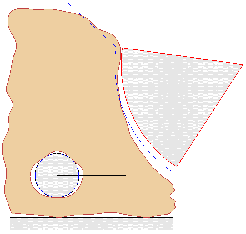
If "valid" means clearly defined and inspectable, then I would contend that the position tolerance is valid. The specification defines a particular boundary, and the surface must be on a certain side of that boundary. We could even make a functional gage to check it: (the thin blue lines are the basic part geometry)

MMC_on_Non-Enveloping_Surface_-_Actual_1_f0nvyc.png


The surface interpretation is sufficient. We don't need to apply the axis interpretation, which would require establishing an unrelated actual mating envelope.

So I agree that this "position" application is technically not within the rules of Y14.5, and is not very useful on its own. But if it were specified, we could verify conformance to it.

Evan Janeshewski

Axymetrix Quality Engineering Inc.
 
semiond said:
If i'm wrong, i will be glad to learn otherwise
For the last two days I have been doing nothing but trying to say it is otherwise ;-)

The concept we are discussing here has in fact very little to do with inspection - it is all about understanding what the actual mating envelope really is and even more about what the feature of size really is. I can only repeat - your argumentation, whether you mean it or not, leads to the conclusion that position tolerance applied to an arc less than 180 degrees is valid callout according to ASME Y14.5. I am not sure we want to follow this path.

Evan,
I thought you might want to discuss on what the word "valid" really means ;-) So let me put it this way without going into semantics. One of the fundamental rules given in para. 1.4 in Y14.5 is that dimensioning and tolerancing shall be complete so that there is full understanding of the characteristics of the feature. In this case the feature is not fully defined for its location that is why the combo does not meet this rule.
 
Axym,
I'm a little confused by your explanation. You describe an application where a position tolerance controls a one sided boundary. Per my understanding, position is a tolerance of location. To locate something, you need a limited tolerance zone. I'm less familier with the boundary iterpretation of position, but if i'm not mistaken, it should lead to a limited tolerance zone, that is usually equivalent of the axis interpretation. The fact that establishment of an UAME is not required, doesn't mean that a boundary that limits only one direction of deviation for the surface (outside the material in this case) can locate the arc. It looks more like a form control to me (* edit - "perfect form at MMC/ rule 1", perhaps). My opinion is - if the boundary interpretation can't limit the translation of arc inside AND outside the material, only axis interpretation is valid in this particular case.
 
Status
Not open for further replies.

Part and Inventory Search

Sponsor