Continue to Site

Eng-Tips is the largest engineering community on the Internet

Intelligent Work Forums for Engineering Professionals

  • Congratulations cowski on being selected by the Eng-Tips community for having the most helpful posts in the forums last week. Way to Go!

True Profile Definition

Status
Not open for further replies.

pmarc

Mechanical
Sep 2, 2008
3,227
Hello,

Below is a snapshot taken from the most recent Tec-Ease tip available on their website. My question would be following: Does anyone think that the true profile between points S and T (clockwise) has not been fully defined? I am specifically thinking about close vicinity of points S and T. Thank you!
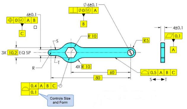
capture_bjnd61.jpg
 
Replies continue below

Recommended for you

Interesting enough, on other Tec-Ease tip for the same part, they have no callout for the outer shape.
Looks like, back in 2000 (when 2009 standard was in development) they developed this tip with no all around profile.
Then, someone complained about lack of complete definition and they added all around profile (which has been proven to be incorrect). Then, they revise it to in between profile which we are discussing now, which is not quite correct either.
That is my pure assmption on why we have soooo many itterations of the same drawing.
 
CH - I'm a little confused by your post because it doesn't seem supported by the standard, at least to me.

I agree that the part of the standard you quoted seems to almost support what you are saying, however it is refuted or at least contradicted by the sentence before it defining true profile as "[...] a profile defined by basic radii, basic angular dimensions, basic coordinate dimensions, basic size dimensions, undimensioned drawings, formulas, or mathematical data, including design models.". It is not clearly stated what exactly is allowable as a "refinement" of size dimensions but I would take it to mean any case where the actual true profile is not defined by toleranced dimensions and only the location of the true profile is affected by said size dimensions.

I would say this due to the fact that there are only 2 types of examples of mixing toleranced/basic dimensions with profile:

1) Fig. 8-17/8-18 => theres much debate on these figures (esp. 8-18) and I won't argue whether they're acceptable only that the REASONING is probably that the true profile of a cone is fully defined by the basic angle and can therefore shift withing the toleranced dimension

2) Fig. 8-27 => the true profile of the one side with a profile tolerance applied is fully defined as a plane, no basic dimensions are needed. and can therefore shift within the toleranced dimension

In the example pmarc showed I would think that the all-around symbol implies that the true profile encompasses the entire rectangular feature, and the toleranced dimensions applied now mean that the true profile is defined by a mix of basic and toleranced dimensions, therefore in my mind violating the aforementioned definition of true profile.

That is just my novice take on it though - please let me know what you think of my reasoning.
 
greenimi said:
Interesting enough, on other Tec-Ease tip for the same part, they have no callout for the outer shape.

Right. This is because it had nothing to do with the point of the tip. Just exactly like the current one. This is also why there are many incomplete figures in the standard. I'm sure if Don had thought his tips would be criticized for things that have zero to do with the subject matter of the tip he would have either added a note like 1.1.4 or he would have put everyone on his mailing list and gotten everyone's approval before posting such heresy as this.

John Acosta, GDTP Senior Level
Manufacturing Engineering Tech
 
powerhound said:
This is because it had nothing to do with the point of the tip. Just exactly like the current one. This is also why there are many incomplete figures in the standard. I'm sure if Don had thought his tips would be criticized for things that have zero to do with the subject matter of the tip....

True. But for some reason or another, Tec-Ease decided to add the all around profile.... and since it is a reputable GD&T training company we have some expectations (I personally do) to have it done correctly (per the applicable standard)....hence the change history from all around profile (change also accepted by Tec-Ease) to in between profile and further......

It is continuous improvement and continuous education.

 
@chez:
I posted my interpretation to agree with drawoh, asking "Is that wrong, or just poor quality?"
You can make part shown on pmarc's example and you can quality-check it.
As long as you accept the idea of profile being the refinement in presence of directly toleranced size, everything falls in place.
By no means I endorse this way as preferred method, just the one that is possible to interpret.
Three sides of the rectangle are completely controlled by profile, while the fourth one depends on size tolerance for location and profile for orientation / form.
Please note (one more time) that location, orientation and form of fourth side all can be measured according to the drawing.

"For every expert there is an equal and opposite expert"
Arthur C. Clarke Profiles of the future

 
CH -- in your sketch you use red to indicate the profile tolerance. So if the actual surface of the part must fall within the red zone, which wraps all the way around that cutout, then the size tolerance (your blue color) makes no sense. You can't make a part that goes beyond the red zone. The key here is the all-around symbol. (Edit...why do you say only 3 sides are controlled by profile?)

Regarding that drawing given by pmarc which has plus/minus tolerancing on the width of the cutout, allow me to get in my favorite dig on the Y14.5 standard...

Figure 8-18 in the standard has the same problem. Imagine pmarc's cutout fully rounded to become a cylindrical hole. Having a plus/minus tolerance on that hole's diameter would not constitute a true profile, thus it would seem to violate the standard. Well, that's the same goof they make in Fig. 8-18! (An aside -- I don't think I have a problem with Fig. 8-17, because that profile tolerance isn't pinned down to datums. Thus, the profile tolerance shell can scoot around until it fits the cone; it doesn't need a basic diameter.)

John-Paul Belanger
Certified Sr. GD&T Professional
Geometric Learning Systems
 
CH,
The image is my modification of one of the figures in the standard prepared just for the purpose of this discussion.

I still do believe that it has nothing to do with tolerance values. True profile of the hole has not been fully defined with basic dimensions which makes the profile tolerance zone created by the all-around profile callout variable in terms of its size and form. That is why I think it is invalid.
 
pmarc,
Quick and direct question:
If 6mm would be made basic, do you think that a basic vertical distance between the two arcs on the left side of the R10 feature is still needed? (as it would if 6mm is kept ± direct toleranced dimension and profile between points are to be used)
 
greenimi,
If 6 was basic then I do not think basic vertical distance between the two arc would be needed.

CH,
Just one question to make sure I understand your replies correctly: Are you saying that my recent example is interpretable as long as the tolerance for 65 dimension is greater than 0.25?
 
pmarc said:
If 6 was basic then I do not think basic vertical distance between the two arc would be needed.
So what makes implied tangency between the arcs and the 6mm features go away in case of 6mm being ± direct toleranced dimension? Just curious.
 
Exampl_rw6fdo.png


CheckerHater,

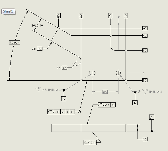
This is not real. I threw it together very quickly to illustrate my point. I have a profile tolerance going all the way around. I have an accurate width applied to one portion of the outline. The profile applies all around. The [±][ ]dimension provides an additional control. On the 20mm width, the profile tolerance controls position.

--
JHG
 
It is simply the fact that 6mm width directly toleranced dimension is not basic.

The problem with Chapter 1 in the standard is that it shows dimensioning practices but does not go deep into details of specific applications. So in fact it should not be read as a stand alone piece of information. Otherwise someone may think, for example, that because in figure 1-6 vertical dimension 12 is not shown basic it is perfectly legal to apply directly toleranced dimensions to locate features of size. Unfortunately, many people do use figures from this chapter to prove that this is true.
 
pmarc,
OK. Thank you.
I understood your point of view. I agree with your statement about the location of a feature of size.
However, I am not sure I agree with the extrapolation and extension to the implied tangency. Hmm... I have to think about this more.
Maybe you are correct. Just maybe for now.....


@pmarc:
"Interpretable" would be a good choice of word. Not "recommended", but something you could get away with.
Not something you should put on your drawing, but way to interpret someone else's drawing.
More "poore quality" than "wrong" on drawoh's scale.
@drawoh:
On your drawing I'd rather see basic 20 dimension, so the entire part is defined by profile.
Your size then will provide additional control, similar to "unless specified otherwise" requirement.

"For every expert there is an equal and opposite expert"
Arthur C. Clarke Profiles of the future

 
CH,
The thing is that on my illustration even if the tolerance for 65 dimension is less than 0.25, the scheme is still interpretable, if we follow the logic you described in your previous replies.
 
CheckerHater said:
Not something you should put on your drawing, but way to interpret someone else's drawing.

I would agree that the intent is "interpretable" and one could possibly come up with a method to inspect the part, but I would disagree that this is an allowable interpretation of the standard. Like I said, the way I read it such practice is not allowed by the definition of true profile.

Per Belanger's comments the key is the toleranced dimension is wrapped by the all around symbol. Along with that is the other key issue is that mixing of a toleranced dimension abutted to a basic dimension and trying to figure out how that applies to a uniform profile tolerance is confusing at best. Just another reason why I don't think this is just "bad practice" but is instead not correct per the standard. Maybe you have a method of interpreting it but I think it might raise more questions than answers (ie: only half the tolerance zone is usable - but does this only apply to the straight portion or the corner radii as well?)
 
pmarc,

To me, an accurate tolerance on 65mm makes sense, even with the profile. The profile controls the position of the FOS. If you went 65[±]0.5, there would be no way to exploit the [±]0.5 without violating the profile. This is the point of my figure.

--
JHG
 
drawoh,
I would really like to avoid repeating once more why I think such mix is not correct.

For the same reason your illustration does not look correct to me too, regardless if the tolerance value for the 20mm width is ±0.10 or ±10.0.
 
I really don't want to enter lengthy discussion here.
Why don't we just re-read Para. 8.2
"Profile tolerances are used to
define a tolerance zone to control form or combinations
of size, form, orientation, and location of a feature(s)
relative to a true profile"

Does it say that profile should always control everything? I don't think so.
"A true
profile is a profile defined by basic radii, basic angular
dimensions, basic coordinate dimensions, basic size
dimensions, etc. etc."

Does it say it should be defined completely? Or it should have enough basic dimensions to control size, form, orientation, location and/or several possible combinations thereof?
If it does, please show me.
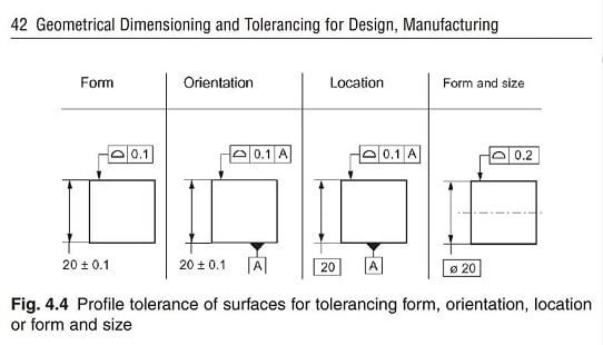
So far I can see that even in the simplest of applications "true" profile may be defined several different ways:
Profiles_r9xuwe.jpg

I know I probably didn't convince anyone, let's just agree that different opinions can co-exist. Maybe future release of the standard will have more robust definitions, but I am not keeping my fingers crossed.
:)

"For every expert there is an equal and opposite expert"
Arthur C. Clarke Profiles of the future
 
Status
Not open for further replies.

Part and Inventory Search

Sponsor