Continue to Site

Eng-Tips is the largest engineering community on the Internet

Intelligent Work Forums for Engineering Professionals

  • Congratulations cowski on being selected by the Eng-Tips community for having the most helpful posts in the forums last week. Way to Go!

torque and power calc for rolling set rig

Status
Not open for further replies.

willtech

Automotive
Feb 23, 2011
4
Hi ENG tips.

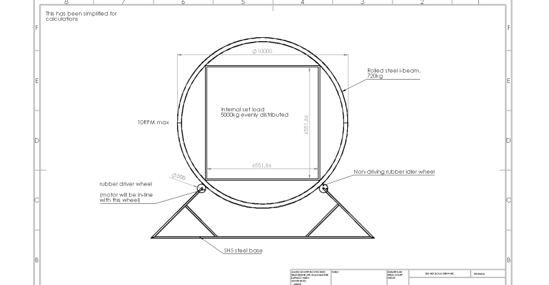
I am designing a large rolling rig which is essentially used to house and turn a film set. In essence it is a base frame with a motor connected to a drive wheel which in turn is acting on a large 10 meter diameter ring. It is within this circular ring that a set would be built.

I am in early stages of design and would like to spec a motor early to help with the drawing process. I have simplified the rig onto one plane (see drawing)in the hope someone can feedback with a suitable calc for motor torque and power post gearbox?

Here are a few details regarding the rig-
10 meter diameter ring 720kg.
rubber drive wheel 500mm diameter.
needs to rotate at 10rpm max.
maximun 5000kg internal load of set, performers etc... this should be evenly distributed but with performers and crew running around this could change a little so redundancy might be wise.
Please see attached images, one of existing rig to give you the idea and one very early drawing of the rig i am designing.

Any help greatly appreciated!!! :)

Existing_roll_rig_dcsmsr.jpg
roll_rig_motion_test_qxqh8e.jpg
 
Replies continue below

Recommended for you

IFF the internal set mass is truly "evenly distributed", then the torque required for any rotation is nearly zero (i.e. just enough to overcome static friction at the bearings).

The reality is that there will never be an even distribution of stuff inside the ring, and, worse, if you have live actors moving around the distribution will vary in time. You will need to come up with some worst-case numbers of imbalance, and use those to design the driver (and brakes).
 
Not at all my area of expertise (if any) but a key number for you is going to be what acceleration you need to achieve.

Regards,

Mike

The problem with sloppy work is that the supply FAR EXCEEDS the demand
 
SnTMan,

I might come at this from the opposite direction. If there are people in this thing when it is actuated, violent acceleration may be a safety hazard. I would work out the maximum acceptable acceleration, and specify a motor not capable of the required torque.

I have no idea of how safety conscious people are on movie sets.

--
JHG
 
rawoh, as I said, NOT my area. Only attempting to point out the stated 10 rpm, alone, is fairly meaningless.

I expect I will withdraw from the discussion now, as I am quite confident I have nothing further to add :)

Regards,

Mike


The problem with sloppy work is that the supply FAR EXCEEDS the demand
 
You may consider this:

model the platform + innards as a cylinder of appropriate mass.
To rotate the cylinder about the central longitudinal axis: T = J x α
J = mass moment of inertia of cylinder
J-cylinder = 1/2 x mass-cylinder x radius-cylinder
α = angular acceleration of the cylinder for the motion required,
is approximated by ( Δ-rotational velocity ) / ( Δ-time to achieve desired rotational velocity )
Spec your motion profiles to get these values to calculate α

That, plus fudge factors for friction, etc., will give the torque required to rotate the inertia.

From that, you'll have to treat the friction drive wheel on the outside periphery of the ring sort of like a gear set, and figure out the torque to drive the wheel through a gear reduction ratio that will impart the needed torque to the cylinder.

Spec a gear motor to give you the rotational speed & torque you need. Torque is cheap, buy plenty of it.
Spec a drive control system to give you programmability.
Or get the gearmotor manufacturer Applications Engineering team to do it for you. (SEW-Eurodrive, Dodge, Nord, others).

TygerDawg
Blue Technik LLC
Virtuoso Robotics Engineering
 
As btrue points out if there is truly uniform distribution you need only cover the frictional losses and the acceleration of the mass. Horsepower wise.

But, if this is a dynamic acting stage then I'd consider instead a worse case of probably two people could physically fit on one side but for a conservative build I'd call it three people.

Your motor and gear box needs to lift three people on a 5m moment arm perpendicular to gravity at 5.25m/s using a motor that is 1425rpm.

1425rpm/10rpm = ratio needed
Total gear reduction = 1:142

Your motor gear reduction has to be able to provide the needed torque of the highest loading point as described above. All other points of the rotation need less torque with the exception of the 3 people will need to be restrained from falling(accelerating) by a retarding force equivalent to the peak lifting force. So the same size motor will have to absorb that returned energy.

You will need a VFD to get you the needed speed variations you'll have to have to make the system tenable. You will also need a place to dump the energy that's coming back on the 'down-hill' side. A braking resistor or a regenerative VFD would provide that.

I'd consider NOT using the drive wheel you have as I believe it will be a hazard because it's friction coefficient and the normal force available will be all that can drive or retard the cylinder. If either changes for any reason you could get uncontrolled rapid acceleration that would surely injure a rider. A drop of sweat, the tire burnishing, any oil, a slight deformation of the cylinder, anything, could uncouple the cylinder from its motion control. BAD.

I'd use a belt instead. They tend to be less iffy, and due to their large wrap radius in this case, will have a great deal of friction. A belt would also allow a much less expensive and more adjustable gear reduction.

Keith Cress
kcress -
 
Status
Not open for further replies.

Part and Inventory Search

Sponsor