Continue to Site

Eng-Tips is the largest engineering community on the Internet

Intelligent Work Forums for Engineering Professionals

  • Congratulations cowski on being selected by the Eng-Tips community for having the most helpful posts in the forums last week. Way to Go!

Theoretical Question - Planar Truss Problem 5

comhedoisl

Mechanical
Apr 9, 2020
13
Hi all.

This is an interesting theoretical question from a book of Feodosiev - Advanced Stress and Stability Analysis. It reads like this:

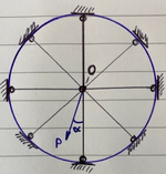
"A plane truss consisting of n>2 equal and equally spaced rods, connected in a common node, O.
The force P acts in the plane of the truss.
Show that the displacement of the node O is always directed along the force P and that the value of this displacement does not depend on the angle /alpha."

The book does provide an answer to this problem, but not with enough detail -- at least from my point of view. I'd like to have a more detailed discussion on this problem with other folks. Could you help me providing your insights?

**the blue circle is not part of the structure
1744903299358.png

Thanks.
 
Replies continue below

Recommended for you

Congratulations comhedoisl, you were correct.

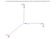
Duh!! Thinking about it last night, I realized that Node "O" had to deflect upwards since member 3 is in compression and is pinned at the top. Now we have the proof thanks to Retrograde and goutam-freela. Thanks guys!
 
yeah, but ... you've modelled the spokes as beams, and the lateral one is picking up a lot of load. If axial rods then the result would be "different" (for the load given it would all be reacted by the aligned spoke; for different loads each spoke would react the component load).
 
yeah, but ... you've modelled the spokes as beams, and the lateral one is picking up a lot of load. If axial rods then the result would be "different" (for the load given it would all be reacted by the aligned spoke; for different loads each spoke would react the component load).
The members are not modeled as beams. They are hinged at each end, so they must act as axial rods. If as you say, horizontal member #2 carried most of the applied load, it would stretch by delta = FL/AE which would be inconsistent with the strain in Members 1 and 3.
 
i was referring to this pic (from reply 19) ...

Screen Shot 04-28-25 at 11.37 PM.PNG

... which I read as 6.8 kN axial load in one member and 3.2kN shear in the other, so the members have bending stiffness (to support shear loads) ...
and the FB looks "off" ... I see the 3.2 kN creating an unbalanced moment about the load, and the 2.4 kN couple also unbalanced ... unless there are end moments not shown.
 
i was referring to this pic (from reply 19) ...

View attachment 8817

... which I read as 6.8 kN axial load in one member and 3.2kN shear in the other, so the members have bending stiffness (to support shear loads) ...
and the FB looks "off" ... I see the 3.2 kN creating an unbalanced moment about the load, and the 2.4 kN couple also unbalanced ... unless there are end moments not shown.
  • 6.8 kN is intended to be the tension in member 2. It's a little off due to the slight change in slope.
  • Reactions at the bottom of member 1 have a resultant aligned with the member. They are a little off due to change in slope, but there is no shear in member 1.
  • There are no moments anywhere because all members are pin-ended.
 
There's a quite simple proof of the original problem statement. As this proof is based on simmetry, it proves also that the same statement won't be generally true in the lack of simmetry.

1) Assume the angle alpha is zero: because of simmetry, the statement is true
2) Assume the angle alpha is the bisector of the angle between two adjacent spikes: again the statement is true because of simmetry
3) Now any load P directed in between the angles in 1) and 2) can be decomposed into two loads, one directed as in 1), the second one as in 2).
4) Each one of the two decomposing loads will cause a displacement directed as the load itself with magnitude proportional to the same load (of course we are in linear elasticity here)
5) In conclusion, the vectorial sum of the two displacements will be directed as the load P and its magnitude will be proportional to P, hence independent of angle alpha.
 

Part and Inventory Search

Sponsor