Continue to Site

Eng-Tips is the largest engineering community on the Internet

Intelligent Work Forums for Engineering Professionals

  • Congratulations cowski on being selected by the Eng-Tips community for having the most helpful posts in the forums last week. Way to Go!

Tension on Bolt of a seated angle 5

Status
Not open for further replies.

1davek

Structural
Feb 21, 2009
6
Learning the basics sometimes is frustrating. Everyone uses it but no one knows where it really comes form.

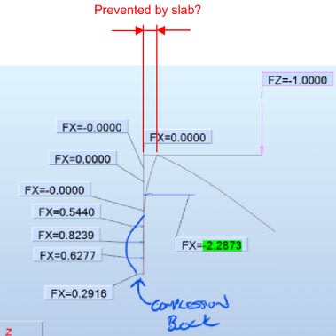
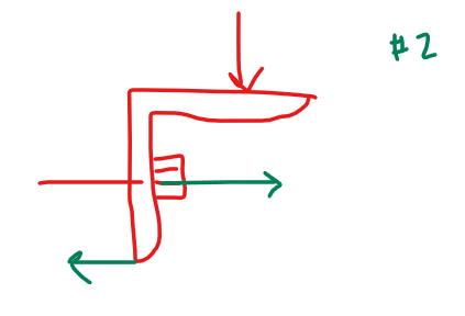
On the left diagram, What is the proper name of the triangle in sketch below.
Why do we assume it to be a triangle.
What is the supporting document that allows this assumption.
Why isn't it like sketch #2 below.

Screenshot_2023-02-23_170504_xiligt.png
Screenshot_2023-02-23_170504-2_gpf9ib.png
 
Replies continue below

Recommended for you

exactly why I need to read the Help file [bigsmile]

Sorry 1davek, derailed your thread here a bit, let us know if we got this cleared up for you or if you need some additional information.
 
1davek... excellent thread... thanks

-----*****-----
So strange to see the singularity approaching while the entire planet is rapidly turning into a hellscape. -John Coates

-Dik
 
I'm curious if anybody considers the following restraint when establishing the anchor forces. I remember many years ago trying to select post-installed anchors in this configuration and I couldn't get anything reasonable to work. An older engineer pointed out that the the anchors wouldn't be in tension. With that assumption, "normal looking" anchors would work. I've seen something similar several times on delegated stair designs; when I've considered tension plus shear, I've gotten stupid-big-looking brackets and anchors compared to what are typically used.

When I design brackets with dubious horizontal restraint, such as with grating or a horizontal slip connection, I consider tension on the anchors.

Angle_Figure_wp2v5v.jpg
 
I'm not aware of anyone that does... but if the angle is secured to the slab, the load on the bolt would approach the 'pure shear' condition of the supported load. Not including it just adds a little more of a safety factor for a connection that could have a lot of variables.

-----*****-----
So strange to see the singularity approaching while the entire planet is rapidly turning into a hellscape. -John Coates

-Dik
 
here it is with a 2.5 kip pre-load on a 4" long 1/2" diameter steel anchor rod (pre-load accomplished with a thermal gradient):
Screenshot_2023-02-25_141122_uqrlcm.png

Screenshot_2023-02-25_141201_p0cion.png

Screenshot_2023-02-25_141355_kmxkrd.png
 
271828 said:
I'm curious if anybody considers the following restraint when establishing the anchor forces.

All day long. I am of the opinion that it is exactly that phenomenon that is keeping things kosher in many a real world application. And I try to bring this condition about whenever I can. It effectively creates a pure shear connection at the supporting member by making the angle a moment connected, flexural extension of the supported member.

I was EOR forced to use these weak orientation connections a bunch of times in my hollow core work as a delegated designer. The only thing that let me sleep nights was that I welded the angles to the plank embeds to create precisely this restraint.
 
1davek said:
Why isn't it like sketch #2 below.

Firstly, it's not like that because of the prying action as mentioned above. That model simply isn't true or universally conservative in most cases.

Secondly it's not like that because one can assume a classic, rectangular stress block at the end of the angle if -- and only if -- the anchor would yield in a ductile fashion before busting out of the concrete. Sometimes that's achievable but, often, it is not.

1davek said:
Why do we assume it to be a triangle.
What is the supporting document that allows this assumption.

The triangle has been traditionally thought to do an adequately conservative job of capturing the prying effect that shows up in Celt's models because:

1) If the bolt is in tension, then surely the neutral axis of the compression block is not higher than the elevation of the bolt.

2) The bolt will always stretch a bit as will the bond/anchorage between the bolt and the concrete, particularly when creep is considered. This means that a gap will form behind the bolt ([unless pre-load - creep] prevents that) and the neutral axis is actually somewhat below the bolt.

3) Folks would typically design the angle leg per your model #2 and limit the flexural stress in that leg to the elastic limit rather than the plastic one. This was an indirect, and imperfect, way to try to make the angle leg "rigid" such that it would be consistent with the triangular stress assumption.

4) Expedience. As interesting as Celt's modelling is, I still don't feel that it's applicable to practical design situations. There are a lot of things about the modelling that will be imperfect in ways that mirror modelling issues with soil springs:

a) What is the appropriate concrete spring stiffness for various member thicknesses? Should it be high/low bracketed? By how much?

b) How is the transition between loaded and unloaded springs handled?

c) What about concrete compression creep?

d) What about gap formation behind the bolt?

e) What about anchorage creep?

f) What about bolt stretch?

g) What about preload?

...

And even if all of that is resolved adequately, you're still stuck with a moving target of a situation that is subject to change when your angle size and thickness change.

The triangular assumption is a well intentioned attempt to create a practical design method from what is really a wildly complex and uncertain design problem.


Were one to attempt to extrapolate Celt's results to a practical design method, one could argue that it, perhaps, ought to be as bad as the sketch below. And even this doesn't fully capture the potential "badness" of it because there isn't even a guarantee that the compression stress in the concrete starts at zero at the toe of the angle leg.
It might start part way up the angle leg as it does in one of Celt's models where the toe of the angle would actually peel away from the concrete. I've seem thing, PEMB base plates in the wild do exactly this for exactly the same reason.

It is for these reasons that I vastly prefer:

1) Angle leg up in the strong orientation.

2) Lateral restraint on the horizontal angle leg.

3) Stiffeners in the angle to reduce the prying action.

C01_ndurro.png
 
canwesteng said:
It could be like the one on the right, if you installed a spacer.

I've longed to do that for years. Have you actually done it? I've avoided the pitch because, before now, I yet to hear anyone other than me suggest it.

C01_z2j3um.png
 
That 'forces' a reaction point, where I've always assumed the reaction is halfway between the fastener and the end (allowing for some flexibility of the angle leg).

-----*****-----
So strange to see the singularity approaching while the entire planet is rapidly turning into a hellscape. -John Coates

-Dik
 
KootK, I don't think I've ever seen the distributed compression load as shown (peaking at the fastener). I've always seen it peaking at the free edge.

I can see that you'd react bolt preload with something like this (on both sides of the bolt), or a uniform reaction.

"Hoffen wir mal, dass alles gut geht !"
General Paulus, Nov 1942, outside Stalingrad after the launch of Operation Uranus.
 
The following figure is copy and paste from the book Advanced Stress and
Stability Analysis ( by V. I. Feodosiev )...


prestressing_concept_yrpyju.jpg


Consider the above spring balance with the top ring has been put on a nail then stretched to 4 kg-f and lower hook placed on the side of heavy rigid table ..The balance indicates 4kg f. Then add some weights to scale . The balance will indicate 4.0 kg f as long as the weights added less than ( preloaded value ) 4.0 kg f.

When the added load is greater than 4.0 kg , say 7 kg, the balance will indicate 7.0 kg ..


P.S.: This post is for just remind the preloading concept and nothing else..


Not to know is bad;
not to wish to know is worse.

NIGERIAN PROVERB
 
I've added spacers in connections to achieve this maybe once or twice, but not in shelf angle connections. Generally an oddball connection where we are particularly concerned about it behaving the way we want it to.
 
Status
Not open for further replies.

Part and Inventory Search

Sponsor