Noob_Engineer
Structural
- Mar 3, 2022
- 2
Hi all,
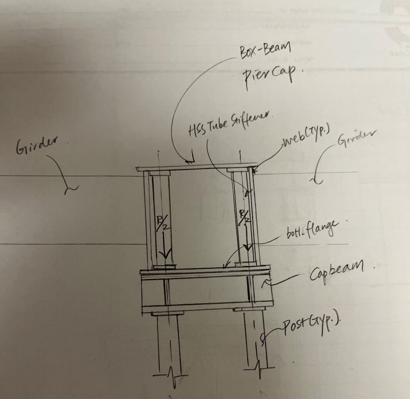
I'm designing a temporary support system to support a box-girder type pier cap for a simple span bridge, using (2) support posts and a cap beam across the top of the post to bear under the box girder. I designed tube stiffeners to be wedged on the insides of the box girder, adjacent to the webs to prevent buckling of the webs from the jacking force/reactions at the location of the support.
I am seeking help just to verify that my thought process is valid and I'm not missing something in the design consideration.
Here are my design assumptions/thoughts:
1. In reality the bottom flange of the box girder won't really be taking any loading, or it would be very little. I think most of the loading will go into the webs & stiffener tubes. In the same vein I am not designing the cap beam for a uniform distributed loading from the reactions because I don't think the bottom flange will really be loaded.
2. I am locating the support posts to be directly under the stiffener tubes because I am making an assumption that the stiffener tube will take the full vertical reactions, and this will eliminate any shear in the cap beam.
Any thoughts and input on this would be greatly appreciated. See attached a rough sketch.
Thank you!