Continue to Site

Eng-Tips is the largest engineering community on the Internet

Intelligent Work Forums for Engineering Professionals

  • Congratulations cowski on being selected by the Eng-Tips community for having the most helpful posts in the forums last week. Way to Go!

Structural Integrity of Pump and Engine Skid Frame

Simba12345

Mechanical
Jul 2, 2023
7
Hi all,

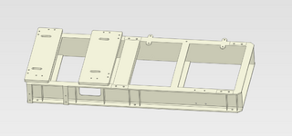
I am a graduate engineer learning FEA, I am doing a simulation on a Pump and Engine Skid frame, I would like your professional input if possible. I have different Ideas on how to apply the loads and boundary conditions, wanted to know if i am on the right path. i am using Prepomax and model was prepared in solidworks. specs are listed below.

Engine Specs:
- power: 297kW
- mass: 1285kg
- RPM: 1800RPM
-Torque: 1560 N.m

Pump Specs:
-mass: 1400 kg

Loads used in FEA simulation
pump weight with 1.5x safety factor = 20.6kN
Engine weight with 1.5x safety factor = 18.91kN
Torque with 2.5x Safety factor = 3900N.m

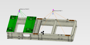
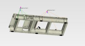
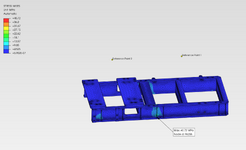
I assigned 2 reference points at the height of the input shaft on the center for both the pump and the engine. the reference points have a rigid body constraint to the pump base (green) and engine mounts (orange). the skid frame sits on 6 antivibration mounts (marked in black) I have used those as the fixed point. lastly, the torque was applied as a moment to the reference points (purple arrows, opposite directions for pump and engine). the last photo shows the results. how accurate are they? how should i go about doing the hand calculations to verify the results?

other ideas i had for the boundary conditions:
- creating reference points at the center of each mounting hole of the frame and setting those as the fixed locations
- applying the weight of the pump and engine directly to the base instead of the reference point (will this be more accurate?)
-adding another reference point for the both the engine and pump at their COG to apply the weight force from there

Thank you all in advance
1745813741530.png


1745813775267.png
1745813884640.png
1745814235965.png
 
Replies continue below

Recommended for you

that FEM looks like gross overkill for that structure.
have you analyzed it by hand so you have something to compare the FEA results to?
do you not have a local mentor?
 
Do you absolutely need to analyze all of those holes? Your geometry would mesh better without them. Related to that, your mesh doesn't look fine enough in the through thickness direction of all of the parts. You generally want at least two elements through the thickness as a bare minimum, although I often shoot for 3 as a minimum.

My gut reaction on your support boundary condition is that fixed supports may be overly stiff and may not give accurate stress or deflection results.
 
As a hand calc, you could beam your two Ref. point loads / torques to the frame (use of BGA). Your frame looks symmetric, so look at one side (neglect cross members). It looks like your torques will load the center of the frame the most. If shown to be the highest applied frame loads, assume the two sets of beamed loads in the middle of the frame goes to the single closest attachment at the base. The load will migrate via shear in the web. Do a local flange bending and vertical shear stress calc at the base attachment flange (could assume restrained in bending at the base of web only, or a rectangular plate supported by web and the two gusset plates). In addition, you could do a beam bending calc along the C section beam and do a VM calc at the base flange attachment (longitudinal flange bending in beam, local flange bending due to bolt attachment load and vertical shear). The fastener may see prying loads. You may also have torsional shear to consider (C beam shear center), although the cross members will restrain any twist. Any torque can be taken out as a couple, between the local top C section cross member and the attachment bolt, by bearing in the flange hole (in addition to assuming torsionally fixed at the local full height cross member).
 
Last edited:
that FEM looks like gross overkill for that structure.
have you analyzed it by hand so you have something to compare the FEA results to?
do you not have a local mentor?
Thank you for your feedback, unfortunately i do not have a mentor yet, I do understand the necessity of having one, I am in search of a mentor currently. I am reading textbooks to upskill and learn more on the topic. rest assured none of the results i obtain will be used to make a decision on the structural integrity of the frame.

could you please expand on why the FEM is a gross overkill for the structure?
 
Do you absolutely need to analyze all of those holes? Your geometry would mesh better without them. Related to that, your mesh doesn't look fine enough in the through thickness direction of all of the parts. You generally want at least two elements through the thickness as a bare minimum, although I often shoot for 3 as a minimum.

My gut reaction on your support boundary condition is that fixed supports may be overly stiff and may not give accurate stress or deflection results.
Thank you for the amazing feedback, i will reduce the element size and add the extra elements for the thickness.
I set the boundary conditions as the center of the mounting holes and that did increase the overall stress that the frame experiences.
 
As a hand calc, you could beam your two Ref. point loads / torques to the frame (use of BGA). Your frame looks symmetric, so look at one side (neglect cross members). It looks like your torques will load the center of the frame the most. If shown to be the highest applied frame loads, assume the two sets of beamed loads in the middle of the frame goes to the single closest attachment at the base. The load will migrate via shear in the web. Do a local flange bending and vertical shear stress calc at the base attachment flange (could assume restrained in bending at the base of web only, or a rectangular plate supported by web and the two gusset plates). In addition, you could do a beam bending calc along the C section beam and do a VM calc at the base flange attachment (longitudinal flange bending in beam, local flange bending due to bolt attachment load and vertical shear). The fastener may see prying loads. You may also have torsional shear to consider (C beam shear center), although the cross members will restrain any twist. Any torque can be taken out as a couple, between the local top C section cross member and the attachment bolt, by bearing in the flange hole (in addition to assuming torsionally fixed at the local full height cross member).
I really appreciate the detailed feedback. I will try to give it a go. could you kindly please suggest any recourses (text books, lectures) that will increase my base knowledge on structural analysis, is there any book with case studies so i can learn the approach used?
 
As I'm in a different industry, I wouldn't want to give you anything that isn't recognized. I do suggest asking your work colleagues about the use of the Bolt Group Analysis (BGA) method, and if there's a standard approach to the analysis of a bolted flange attachment (possible inclusion of prying load). I would expect any hand analysis approach would include the use of an effective length at the base of the flange, to be in bending from bolt loading (flange to web intersection). A good source of hand analysis methods is Roark. I would think this is a universal source of information.
 
My starting point for any dynamic equipment pad / foundation is the ACI document on the subject. ACI 351.3-R Foundations for Dynamic Equipment.... That will give the basic guidance for dynamic equipment and foundation modeling.
 

Part and Inventory Search

Sponsor