Continue to Site

Eng-Tips is the largest engineering community on the Internet

Intelligent Work Forums for Engineering Professionals

  • Congratulations cowski on being selected by the Eng-Tips community for having the most helpful posts in the forums last week. Way to Go!

RBE2 Double Dependency

Status
Not open for further replies.

sirbrandon

Mechanical
Jan 4, 2009
19
Hi,

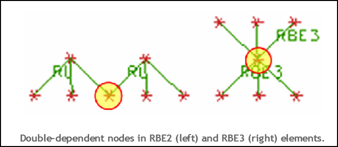
I read about the dangers of double dependency when using RBE2. I have a problem (see attached pic) where I need to mount two components one the same platform, one component on the top surface, the other on the bottom surface. I tried running the sample problem with AUTOMPC ON, and it seems to run ok. Can anyone advise if this approach is ok? How else would you model the problem if I were to avoid having double dependency in this case? Thanks.

rbe2_s1ho8b.png
 
Replies continue below

Recommended for you

Hello!,
I see frequently in FEMAP & NX NASTRAN users the "double dependency" problem, the reason is the lack of knowledge of the rigid NX NASTRAN RBE2/RBE3 elements, please note all are in the manuals!!. Double dependencies occur when two elements share a dependent node. If your model contains double-dependencies, the NX NASTRAN solver may not be able to correctly resolve the degrees of freedom in your model.

double-dependency-rbe2-rbe3_b7fd6a.png


Instead to use the PARAM,AUTOMPC,YES keyword I suggest to take a look to the real problem and consider the use of RBE3 elements instead RBE2: common use for this RBE3 element type include adding and distributing mass without adding stiffness, and distributing a load to multiple points from a single point. Please note the core node of the RBE3 element is the DEPENDENT node.

If this is the case in your example, you can use perfectly two sets of RBE3 elements, not error at all!. Unlike the RBE2, the RBE3 element is flexible (not infinitely rigid), due to the allowable freedom of the leg (INDEPENDENT) nodes.

rbe3_vcdijp.png


Best regards,
Blas.

~~~~~~~~~~~~~~~~~~~~~~
Blas Molero Hidalgo
Ingeniero Industrial
Director

IBERISA
48004 BILBAO (SPAIN)
WEB: Blog de FEMAP & NX Nastran:
 
As you want to use a rigid element with infinite stiffness, just make only one RBE2 with independent the first note of force application and dependent all others grid point ,included the second point of force application. As everything is rigid does not change anything making one or two RBE with sharing grid points.
Another, more complicated way to do what you need is to duplicate the grid points of dependent RBE and connect each other with a stiff CBUSH.
so one RBE will be connected to grid point of shell, the second RBE is connected to duplicated grid points who are connected to the model with stiff Cbush on coincident nodes.
 
Hi Blas, thanks. I've been reading with interest your many helpful posts here in this forum. But in my case, I am trying to model solid components mounted on the top and bottom surfaces of an Aluminium plate, so I thought maybe RBE3 is not so suitable, since both the top and bottom components add rigidity to the Aluminium plate, and RBE3 has flexibility which I thought may not represent the model correctly.

Hi Onda, I don't quite understand your post. The independent nodes are not for force application, but represent the CGs of the top and bottom components mounted to the plate.

Cheers!
 
Hello!,
Then model your solid components with SOLID 3-D CHEXA elements and use GLUE surface-to-surface contact between the solid face and Shell aluminion face, create two contact pairs, one for each face. NX NASTRAN GLUE is a simple and effective method to join meshes which are dissimilar. It correctly transfers displacement and loads resulting in an accurate strain and stress condition at the interface.

The grid points on glued edges and surfaces do not need to be coincident. Glue creates stiff springs or a weld like connection to prevent relative motion in all directions.
Best regards,
Blas.


~~~~~~~~~~~~~~~~~~~~~~
Blas Molero Hidalgo
Ingeniero Industrial
Director

IBERISA
48004 BILBAO (SPAIN)
WEB: Blog de FEMAP & NX Nastran:
 
Hi Blas, thanks for the advice. My original method was to shell-mesh a surface (density 2 orders lower, stiffness 2 orders higher) representing the mating area, and couple the point mass to this surface with RBE2 elements. Then, I GLUE surface-to-surface contact the mating area to the plate. I had thought that this method looks a bit strange, hence I wanted to use the "conventional" method instead. What do you think?
 
I hope this helps a little bit:

You may be correct in that RBE2 may be a better representation if the attached bodies are 'far' stiffer than the plate.

Is that really the case? What difference did you notice using RBE3 vs RBE2?

RBE3 is an interpolation (or soft) element in that it does not over constrain the independent nodes (RBE3 has one 'dependent' and several 'independent' nodes due to the force interpolation dependency, RBE2 is vice versa).

Stressing Stresslessly!
 
Status
Not open for further replies.

Part and Inventory Search

Sponsor