Continue to Site

Eng-Tips is the largest engineering community on the Internet

Intelligent Work Forums for Engineering Professionals

  • Congratulations cowski on being selected by the Eng-Tips community for having the most helpful posts in the forums last week. Way to Go!

Question about Tip-Tilt and Lateral Adjustment

Status
Not open for further replies.

N.More

Aerospace
Oct 7, 2021
4
Question_wnhmav.png


Hello Everyone,

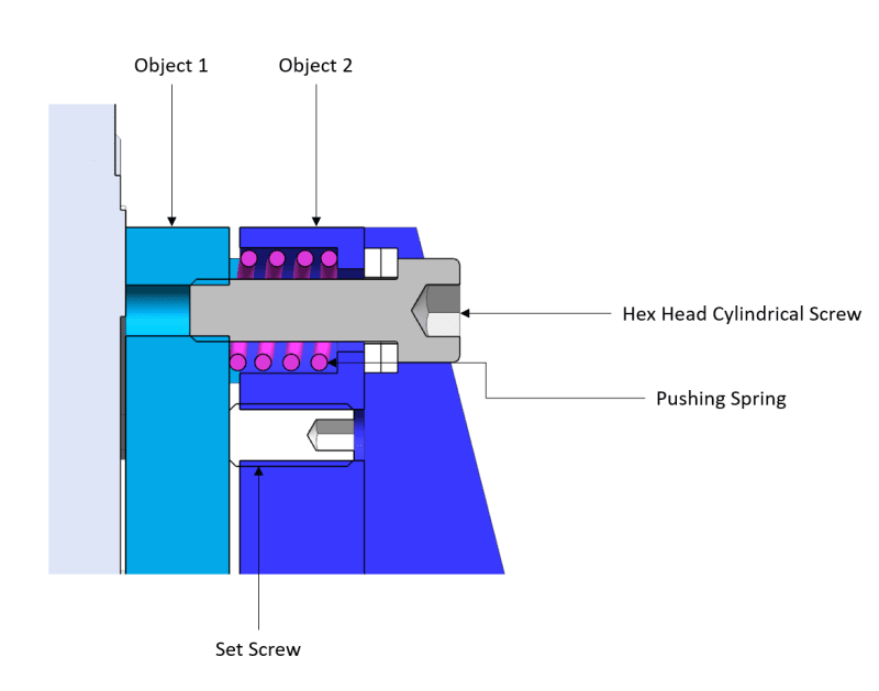
Could someone please explain how the adjustment mechanism shown in the image works?
There should be relative motion between Object 1 and Object 2. I have shown only one screw, so in this case, one should be able to move left and right.
The set screw is seen to make contact and the Hex Head Screw is engaging the thread in Object 1.

How exactly is everything working together here? What is the sequence of assembly here? How do the parts relatively move to either increase or decrease the space between them? And finally, once the desired position is achieved, how is it fixed?

Many Thanks!
 
Replies continue below

Recommended for you

The hex-head screw and spring work together for position adjustment by simply rotating the hex-head screw. The set screw is tightened to remove the compressibility of the spring after the adjustment is complete. There should access to the set screw for tightening. The angled blue surface appears to be a stiffener behind the cap screw, and not a sectioned surface.
 
Thank you. Yes, the angled blue surface is not a sectioned surface. It is indeed a feature to simply add some stiffness to the blue part.
Is such an assembly sufficiently rigid after the final tightening of the set screws? And after the set screws are completely tightened, can one apply 80 - 100% torque on the Hex Head Screw or not?
 
This is a common method of adjusting and then fixing the distance between two parts. The set screw determines the minimum distance. The cap screw determines the maximum distance. By tightening one against the other the distance between the parts become fixed. This is also a common method of attaching adjacent precision machines to a common floor. It allows adjustment, and locking, of their positions for alignment.
 
We use something like that for kinematic mounts. The set screws, in our case, determine the angle and spacing of Obj2 relative to Obj1, and the hex screw holds them together, but allows them to come apart and be re-installed with micron-level repeatability. The set screw would usually go into a steel cup, or somesuch, for hardness considerations, since our Obj2 and Obj1 are typically 6061 aluminum

TTFN (ta ta for now)
I can do absolutely anything. I'm an expert! faq731-376 forum1529 Entire Forum list
 
Socket head screw, not hex head....

The problem with sloppy work is that the supply FAR EXCEEDS the demand
 
Hi N.More

In my opinion one cannot apply 80% to 100% torque to the socket head screws after the set screws are fully tightened because that negates the gap setting on the spring for the two components, the preload in the hex socket screws is determined by the gap between the two components and the compression of the spring.

“Do not worry about your problems with mathematics, I assure you mine are far greater.” Albert Einstein
 
N.More,

Are you designing this thing, or just trying to make sense of someone else's mechanism?

I have worked with mechanisms like this for optical alignment. I don't like the locking screw. It is very difficult to tighten this thing down without disturbing your alignment. Google die[ ]springs. You can order extremely stiff coil springs, which will keep you aligned without the locking screw. The blue painted medium strength die springs have particularly good travel distance with respect to height, while exerting lots of force.

--
JHG
 
Status
Not open for further replies.

Part and Inventory Search

Sponsor