Continue to Site

Eng-Tips is the largest engineering community on the Internet

Intelligent Work Forums for Engineering Professionals

  • Congratulations cowski on being selected by the Eng-Tips community for having the most helpful posts in the forums last week. Way to Go!

Portal Frames and Nailed Moment Connections

Status
Not open for further replies.

medeek

Structural
Mar 16, 2013
1,104
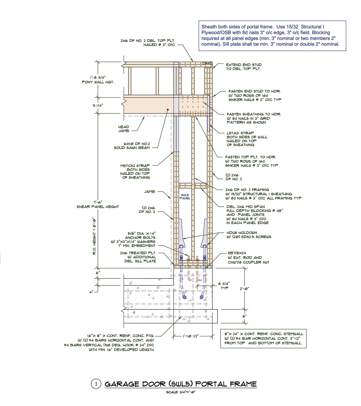
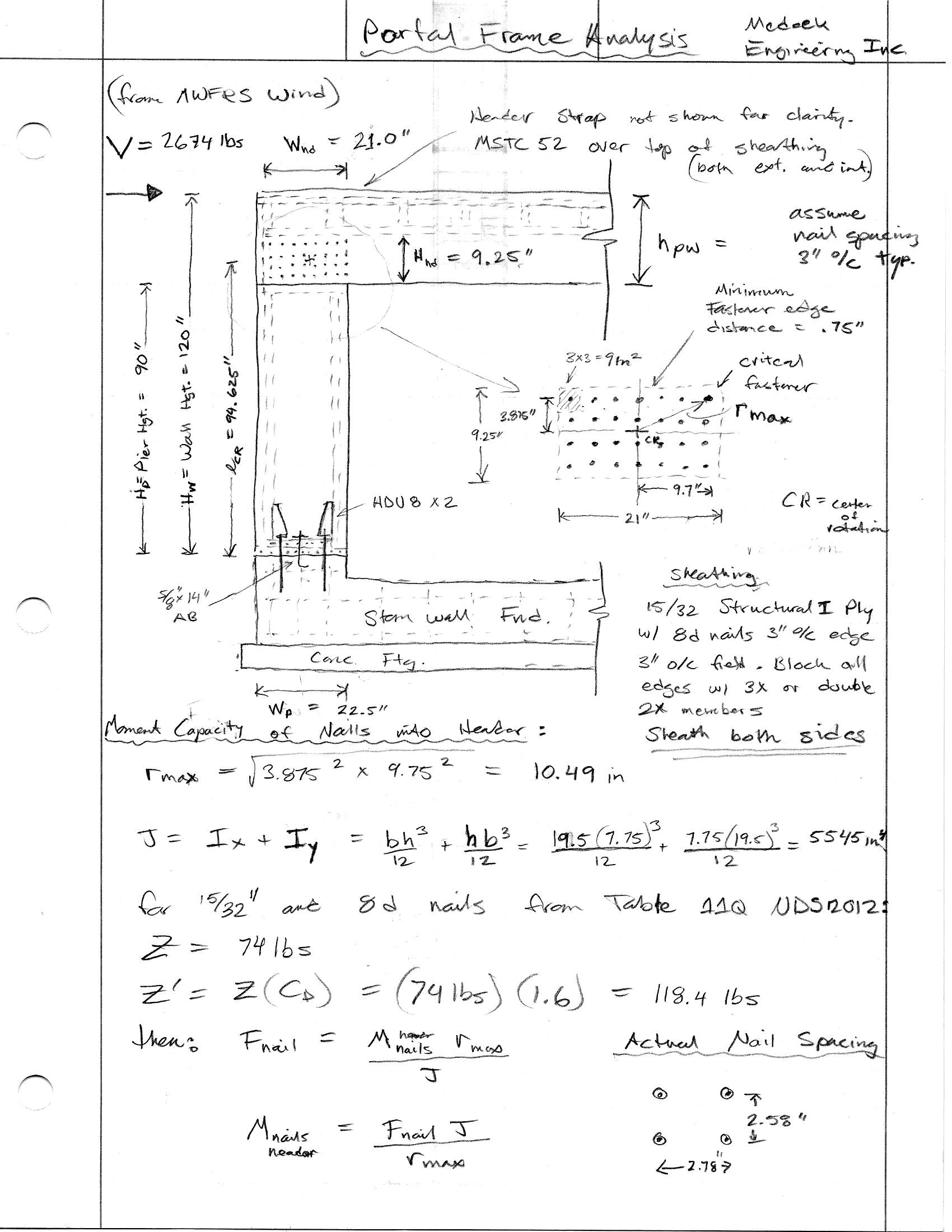
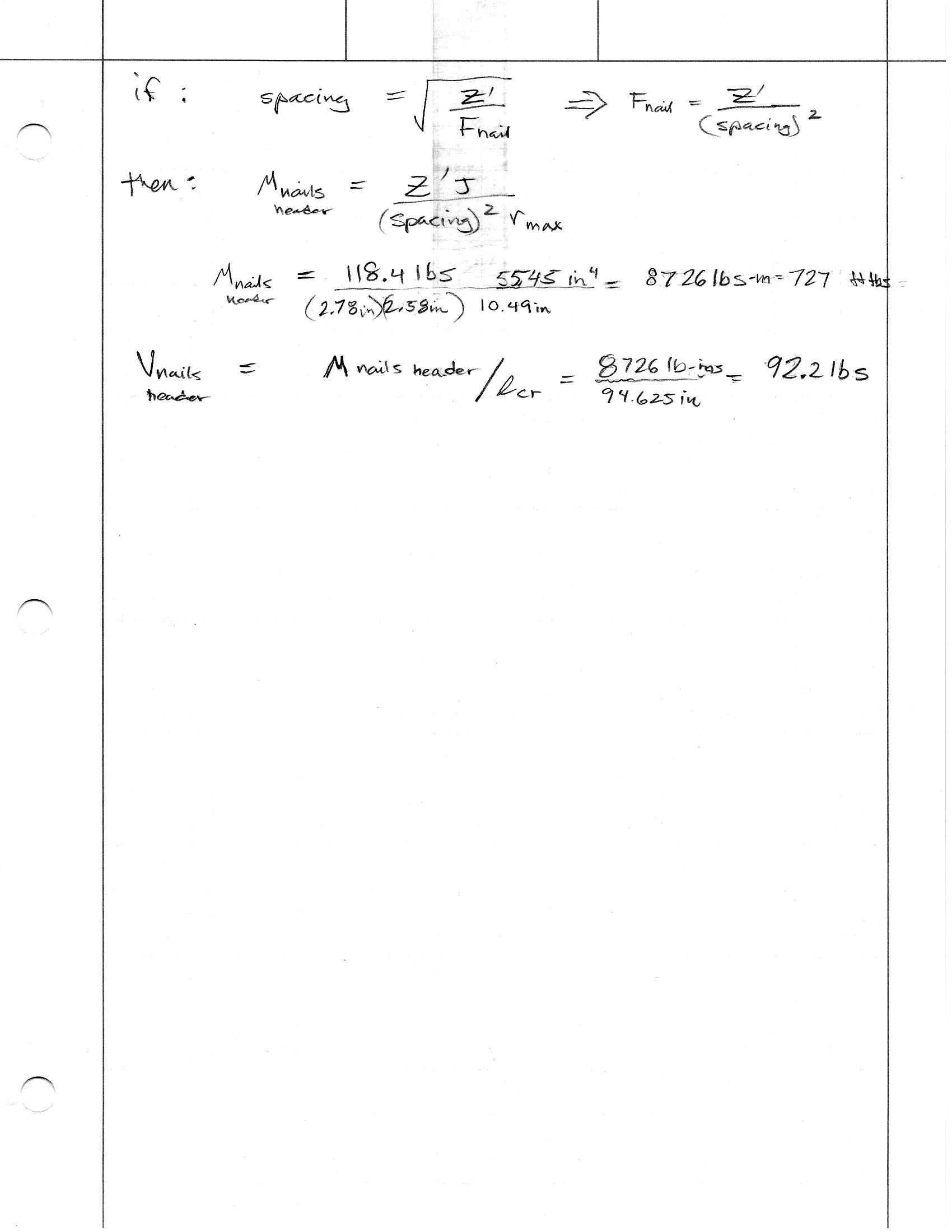
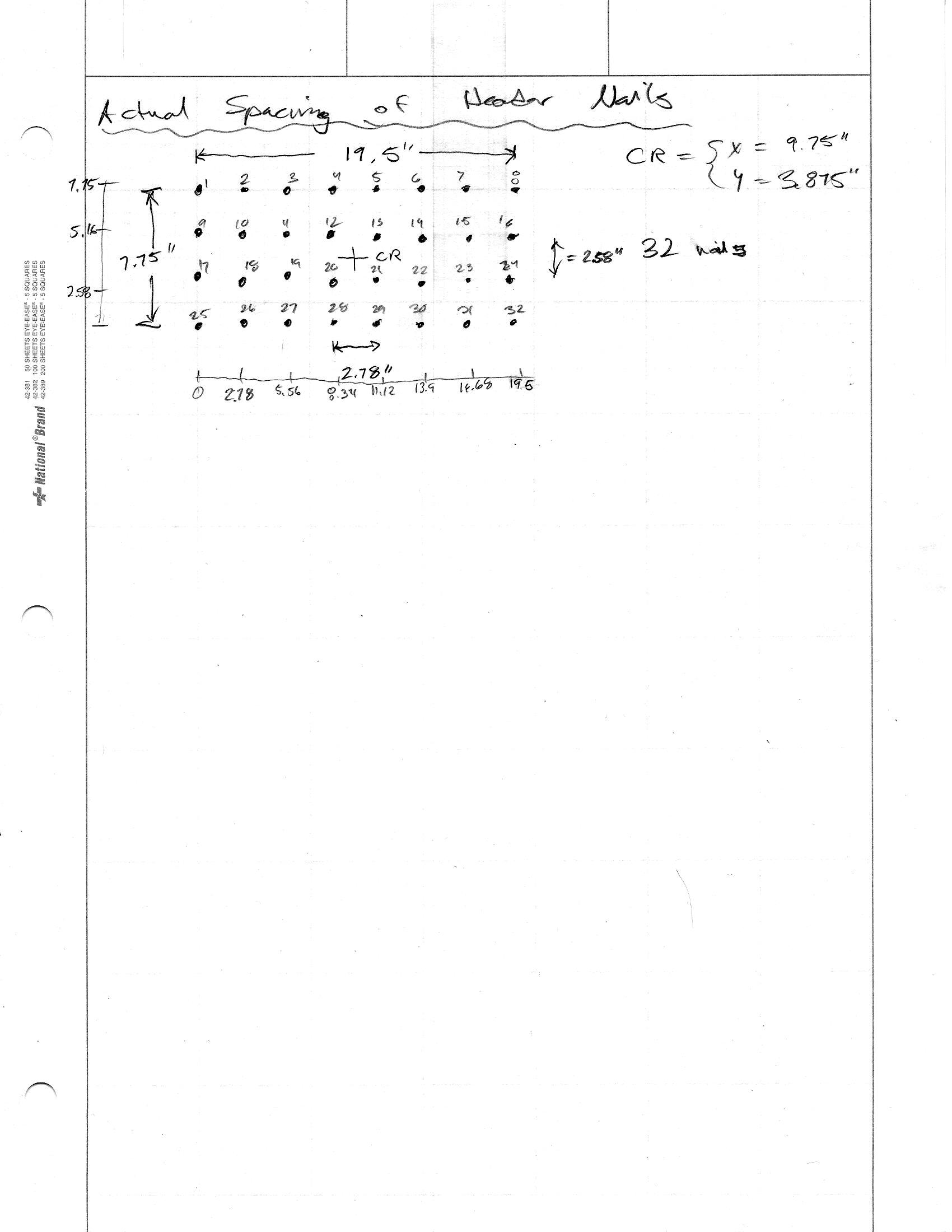
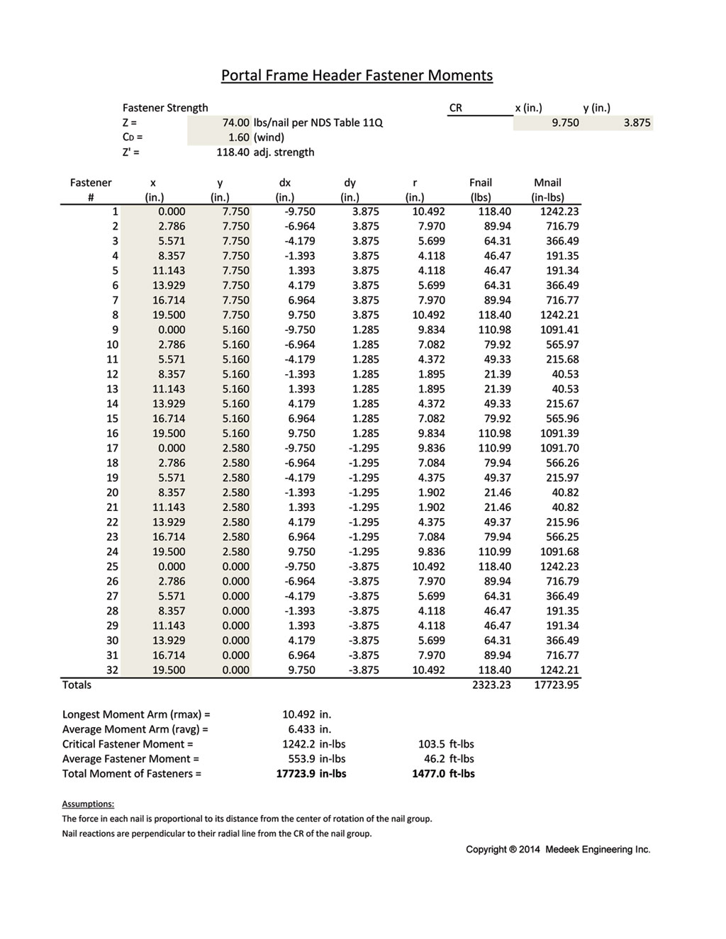
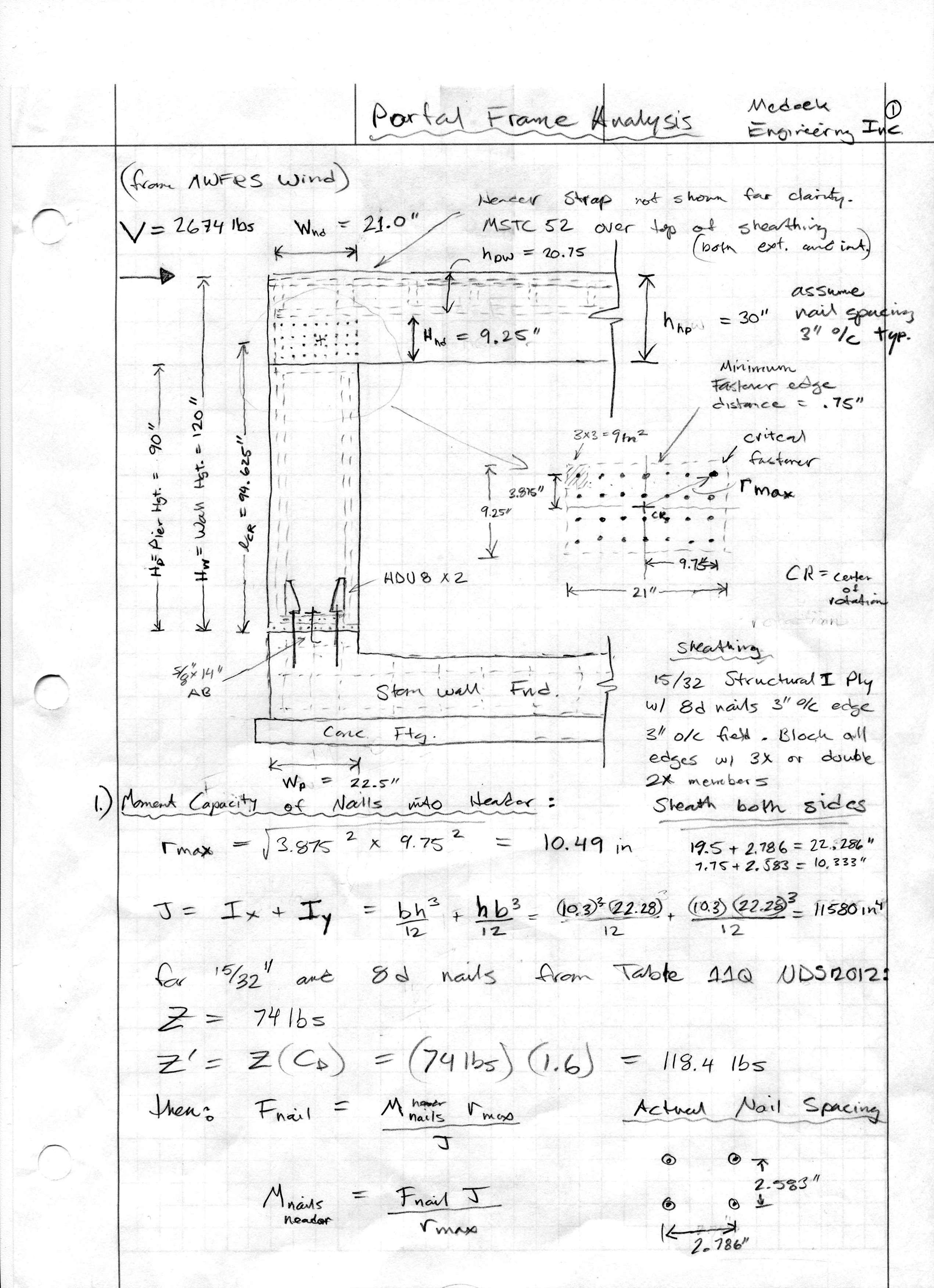
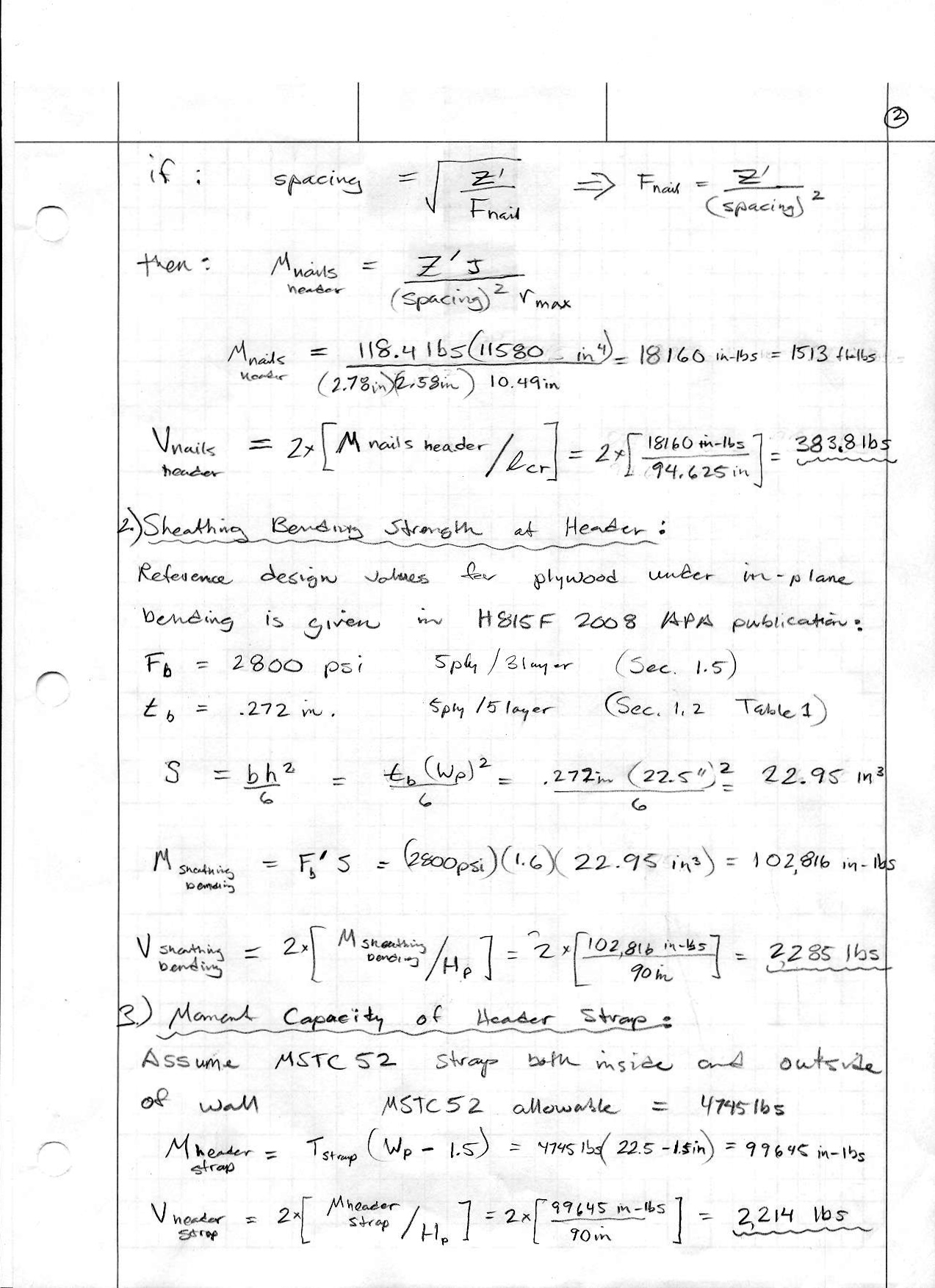
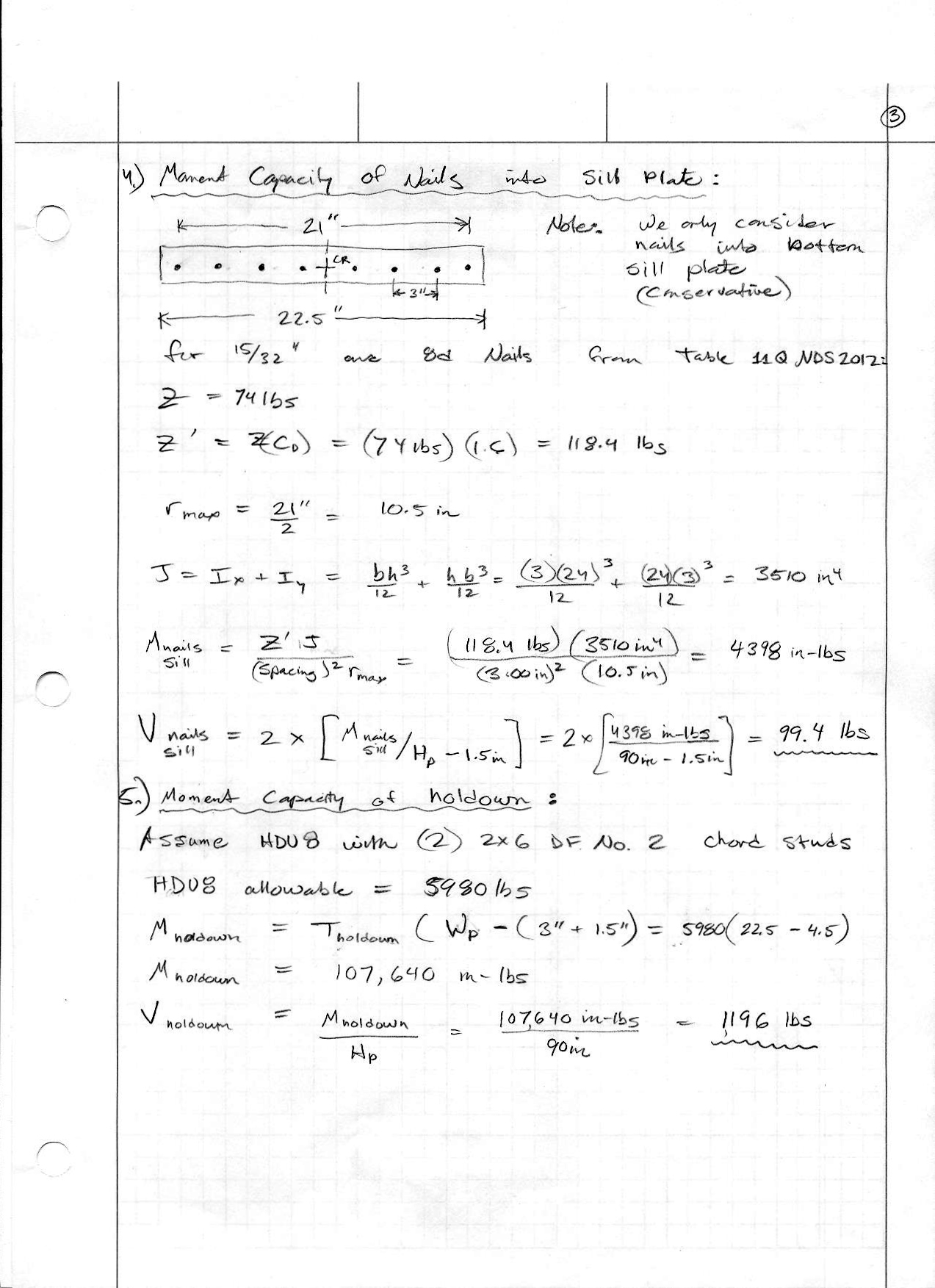
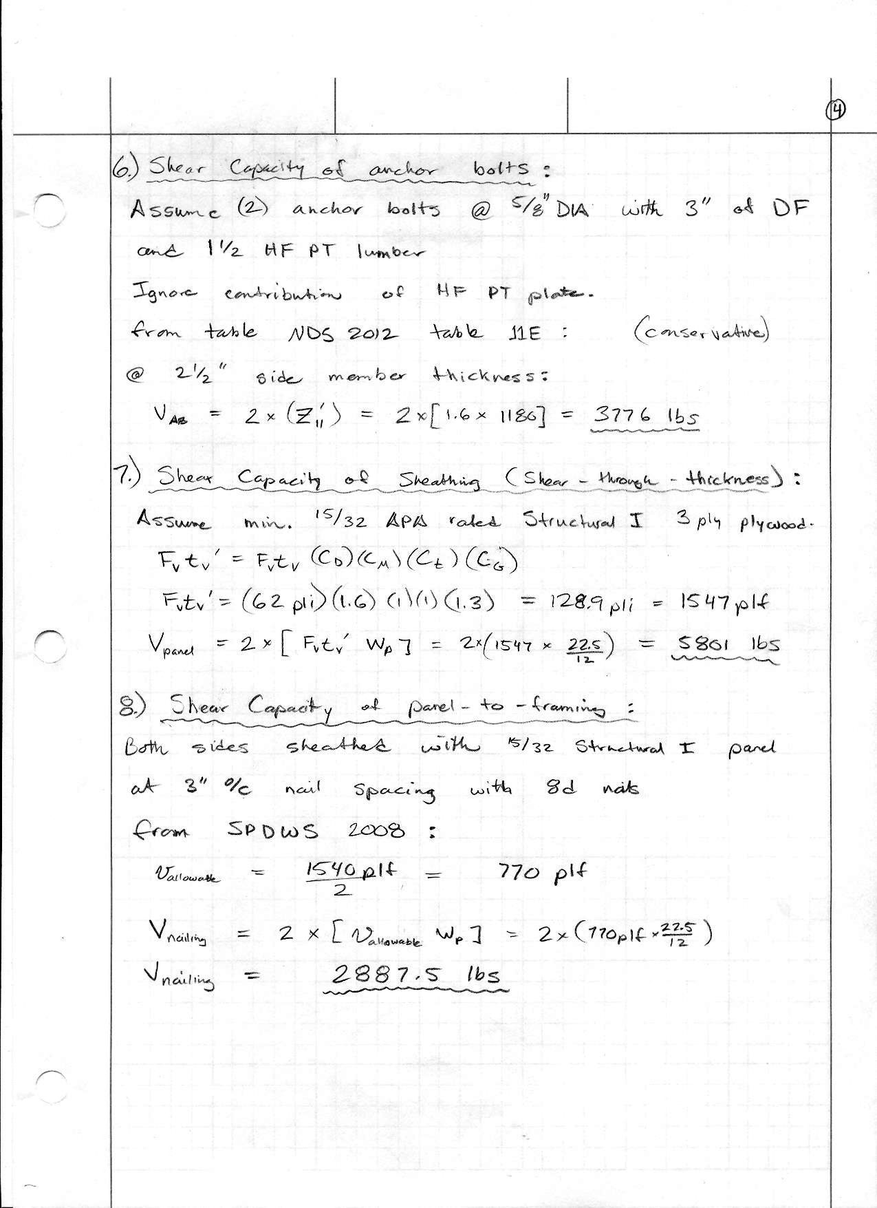
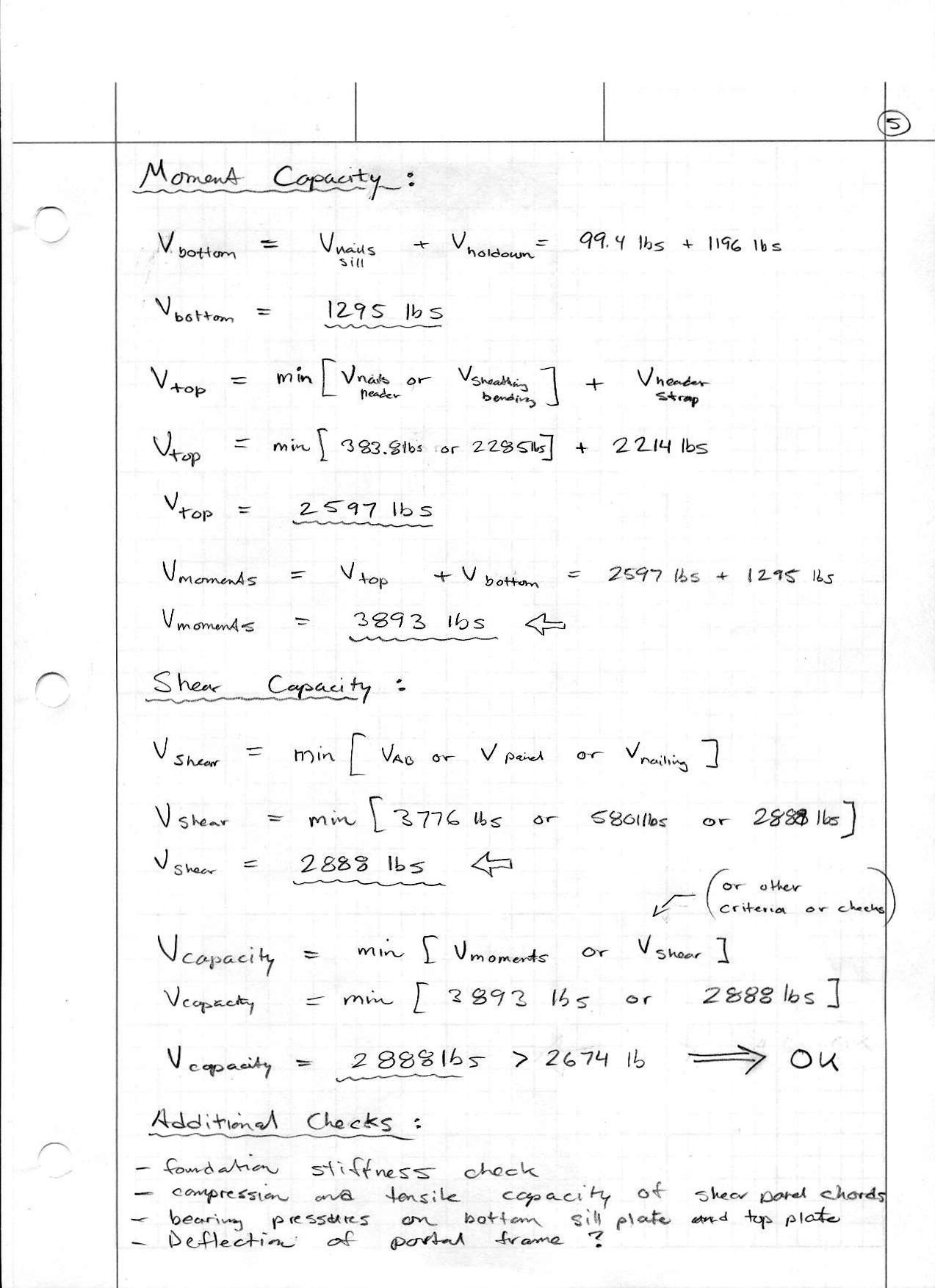
I'm doing an investigation on analyzing portal frames and so far my best resource has been "Analysis of Irregular Shaped Stuctures" by Malone. Specifically I am trying to figure out how to calculate the moment capacity of a group of nails (grid @ 3" o/c spacing) at the connection between the shear panel sheathing and the header of a portal frame. Any suggestions, resources or opinions would be appreciated.
 
Replies continue below

Recommended for you

I may be wrong, but i was always under the assumption that residential portal frames (sounds like what you are talking about) are tested assemblies and are quite difficult or inaccurate to analyze. with that being said... I would think you would be able to turn the nails into a stiffness (group factor required) in the lines of nails and then calculate your Ix and Iy based on centriod of stiffness (think about them like welds). you can then calculate the torsional properties. now use that to determine what the maximum moment is by limiting the stress in the governing line. I have never done this for a portal, but i think it would work :/

 
I agree with EngineeringEric. Calculate the polar moment of inertia of the nail group, and check the most highly loaded nail against the allowable capacity.

DaveAtkins
 
medeek,
I think that chapters 13 and 14 of the book that you mentioned does the best job of explaining design of portal frame design.
For more information check out the "References" at the end of those two chapters in the book. The APA information is all available on line, for free, at:
 
now try to calculate the drift of the portal frame :>
I only use portal frames that are prescriptive. Anything beyond that, I use steel moment frames.
 
The drift should not be too dissimilar from a regular shear wall. The only major difference might be some additional deflection due to bending of the shear panels similar to beam bending.
 
One thing that I found interesting about flexible vs. rigid diaphragms is that the rigid diaphragm analysis creates torsion on the structure and basically adds the additional load into the other three walls. You basically eliminate the third wall (portal frame wall) entirely. So why so much fuss over portal frames, make the diaphragm stiffer, treat it as a rigid analysis and assume the portal frame wall basically does nothing in resisting the lateral load. Breyer's book has a good treatment on this, looks like I need to do some more reading...

The prescriptive bet is the safe bet, I agree. However, I would like to be able to actually engineer one of these with some confidence. If I increase the strap capacities, holdowns, anchor bolts and sheath both sides of the portal frame with 15/32 Structural I Ply/OSB where does that put me? I should be able to get a little more than the prescriptive IBC/IRC portal frame. Consideration for the concrete foundation stiffness and the header stiffness also factor into the design as well.
 
The issue is a wood diaphragm cannot be modelled as rigid. Or at least you aren't supposed to. So your portal frame does take lateral load.
 
However interestingly enough as brought up in another thread we assume the roof and ceiling diaphragm for a 3 sided open balcony transfer the loads back to the main building structure. Not sure how it can act as a "rigid" diaphragm in that case but not in this case.
 
The latest and greatest in wood diaphragm design philosophy holds that, in many instances wood diaphragms can -- and should -- be modelled as rigid. Certainly, there is no code prohibition against it. Many folks also ascribe to the profit sapping bracket approach. I'm still doing flexible diaphragm designs in all cases for reasons better left for a separate thread.

Many designers object to three sided buildings wholesale due to their poor seismic performance history. I'm not one of them. I simply take a great deal of care when designing lateral elements for three sided buildings, particularly with respect to drift.

Diaphragm rigidity is about the relative stiffnesses of the vertical and horizontal shear resisting elements. Viewed in that light, an assumed rigid diaphragm over a spongy moment frame makes sense. A true three sided building diaphragm is rigid by virtue of equilibrium as it is statically determinate.

The greatest trick that bond stress ever pulled was convincing the world it didn't exist.
 
All wood diaphragms are semi-rigid. Semi-rigid diaphragms are time consuming to design so depending on the situation (as KootK noted) it is easier to model them as either flexible or rigid.

Garth Dreger PE - AZ Phoenix area
As EOR's we should take the responsibility to design our structures to support the components we allow in our design per that industry standards.
 
Here is a proposed portal frame, I'm not saying its correct but I'm going to run the numbers on it to see what if anything is wrong with it:

PORTAL_FRAME_ANALYSIS.jpg
 
The start of the calcs shown below:

PORTAL_FRAME_CALCS0002.jpg


PORTAL_FRAME_CALCS0003.jpg


PORTAL_FRAME_CALCS0001.jpg


However, I didn't trust the number I was getting for the total moment of the fasteners from the elastic method so I created a spreadsheet which calculates the moment contribution of each fasteners and then sums them up:

PORTALFRAME_HEADERFASTENERS.jpg


The problem I am having is the two numbers for the total moment capacity of the nails don't agree and I haven't been able to get them to agree. Maybe someone can tell me what is wrong with my calculations in particular the equation M(nails header) = Z'J/(spacing)2rmax.

My feeling is the correct answer is the 17,724 in-lbs given in the spreadsheet, correct me if I'm wrong.

Once I have fully researched this example and possibly a few other configurations I hope to make a comprehensive online calculator that goes through all the tedious calcs and even programmatically determines the nail spacing on the header among other things. I don't think such an app currently exists, but there are a few white papers out there that provide pretty clear guidance.

In addition to the wood engineering other items that should be considered is the deflection and sizing of the concrete stemwall or thickened edge slab footing. The foundation portion should be fairly easy given the direction of the Malone and Rice's text however deflection is not so clear cut.
 
I made a few adjustments to the numbers I was using for the calculation of the polar moment of inertia and now I get M(nails header) = 18160 in-lbs which is within about 2.5% of my spreadsheet answer, close enough.

Then the V(nails header) = 2 X M/lcr = 383.8 lbs since both sides are sheathed.

Note that this value is conservative since I am ignoring the contribution of the nails into the sheathing above the header (into the pony wall), actually probably too conservative for some. This value is only taking into account the nails that are nailed in a grid pattern into the header.

I could theoretically include all of the nails that are in the panel above the header and to the side however the calculation of the center of rotation would become quite complex and I think a conservative approach is warranted where the quality control in the field might be somewhat suspect.
 
Here are the final calcs for the shear capacity of the portal frame. Note that in this case the governing factor appears to be the the sheathing-to-framing connection based on nominal unit shear from SPDWS 2008.

PF1.jpg


PF2.jpg


PF3.jpg


PF4.jpg


PF5.jpg
 
You will notice when looking at the Autocad drawing above that I have a MSTC52 strap on one side of the portal frame and a LSTA21 strap on the other side (approx. 1000 lbs capacity). The idea here is that the single 2x6 king stud to the top of the portal frame takes most of the load when this side of the portal frame is in tension thereby eliminating the need for a large strap on this side of the PF. If you look at the current PFH portal frame with holdowns in the IBC or IRC you will notice that this strap is conspicuously missing, previous editions of the IBC/IRC seemed to have had this strap in their diagrams.

The tensile capacity of a DF No. 2 2x6 is fairly decent especially with a CD of 1.6 applied for wind / seismic loads. However, my engineering mentor pointed out to me that the nails connecting this king stud to the rest of the framing and sheathing will probably fail in shear before the member will actually fail. So then my thought was to just increase the strap on this side to equal the strap on the other side of the portal frame (ie. MSTC52 strap on both sides, interior and exterior, 4 straps total). However, if you look at this the outside strap would mostly be nailed into perimeter king stud and most of its developed strength would rely on this king stud shouldering the tensile load. In other words even with a larger strap the point of failure would still be the nails shearing that connect this king stud to the rest of the portal frame (header, framing and sheathing).

Perhaps I am over thinking this.
 
I think that your points are valid. But then I tend towards over thinking myself. My thoughts:

1) Where does the outer strap deliver its tension load to in the end? To the header? To the outermost stud? I would have expected the path for that portion of the of the tension load to extend right to the top of the portal frame. You could make it do that easily enough by extending the strap over the cripples above.

2) You've got a metal strap and a wood stud working in parallel to resist a common tension load. There may be some issues with stiffness compatibility. Suppose the stud absorbs all of the load initially and snaps, then sheds its load to the strap which then yields or fractures. Or vice verse. I'm not clear how much ductility can be relied upon in this kind of system. This probably is over thought as we seem to disregard such issues in wood construction routinely.

The greatest trick that bond stress ever pulled was convincing the world it didn't exist.
 
So what would be the best option for the outer strap on the portal frame? If you remove it entirely then you are relying on the bending strength of the sheathing or moment capacity of the fasteners plus the tensile capacity of the end king stud which is probably governed by fastener shear into the adjacent framing.
 
To address item #1, I'd run the strap up to engage the blocking above the header.

To address item #2, I'd take all of the load across the strap.

To be honest, I'm not sure that anything needs to be changed so long as you've addressed your load paths thoroughly, As I mentioned above, it's not clear to me where the outer strap tension ends up at the end of the day. It appears to deliver its load into the header.

Certainly, if the outer king stud and it's connections can deal with the entire tension load, I think that it's fine to leave it at that.

The greatest trick that bond stress ever pulled was convincing the world it didn't exist.
 
Status
Not open for further replies.

Part and Inventory Search

Sponsor