krugtech
Industrial
- Feb 3, 2010
- 413
On the newer lasers we use networked PLC nodes. This saves a lot of wiring as only a power and data lead needs to be run around the machine. I've been having issues with this, specifically the power bus. Barley getting 18 volts at the end of the line w 24 volts in. This really freaks out the control. the solution is simple-
Just double up on the power wires, most of the loss is the termination module so simply pass the power to it but NOT through it-
Before-
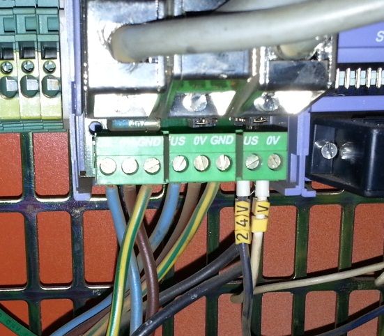
After-
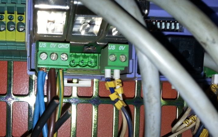
I had a machine yesterday that had 5 of these wired pass-through. Got about 6 volts back at the end of a string of 5 of these. Many "ghost" problems went away.
This is a selectron machine, the Allen Bradly is similar (device net) but they actually have double terminals that plug into the termination nodes, just have to make sure the installer/assembler took advantage of this.
Chris Krug
Chris Krug Maximum Up-time, Minimum BS
