Continue to Site

Eng-Tips is the largest engineering community on the Internet

Intelligent Work Forums for Engineering Professionals

  • Congratulations cowski on being selected by the Eng-Tips community for having the most helpful posts in the forums last week. Way to Go!

Over dimensioning around center lines 3

Status
Not open for further replies.

Oaklandishh

Mechanical
Sep 3, 2014
48
I have a part with a symmetric line down the middle as shown in attached picture.

Assuming I am using current ASME standards, having the dimension labeled 1(red) and the dimensions 2 and 3 would be over constraining the part correct?

Is having only the dimension labeled 1 and not having dimensions 2 and 3 an acceptable way to dimension the part?

What about having only dimensions 2 and 3 and not 1, similar to how dimension 4 is being used?

As a semi related bonus question, if I put in a center line, does that imply the part is supposed to be symmetrical about that line in all views or just in the view with the center line? Can I use a center line on a part that is not completely symmetrical about that axis in the given view as long as the non symmetrical features are obvious?

I have tried looking these up, but I cant find exactly what I want in ASME Y14.5 or a good example on google, sorry if this is obvious and I have just missed it.



 
 http://files.engineering.com/getfile.aspx?folder=396539a4-04ba-4943-aec6-ae9d0d779e2a&file=CenterlineOverConstrained.png
Replies continue below

Recommended for you

You've moved the datum feature symbol away from the dimension line. That changes the meaning of it. Datum feature B is now the right edge of the necked down part. If you look at your previous drawing you had the datum feature symbol in line with the dimension line. That makes the datum the centerplane of the necked down part. You're still on the right track and it looks better but A little more refining needs to be done. Do you happen to have a copy of a GD&T standard available? There's a right way to indicate more tolerance in one direction than the other and this isn't it. A verbal explanation will take a lot so I'm hoping I can just point you to the page.

John Acosta, GDTP Senior Level
Manufacturing Engineering Tech
SSG, U.S. Army
Taji, Iraq OIF II
 
I have a copy of ASME Y14.5M-2009 I can use if that works?

The tip about having the datum on the dimension is very helpful, didn't even occur to me.

 
@Oaklandishh
Not quite how I would set the default tolerance block, but if that's your standard, to each their own.

_________________________________________
NX8.0, Solidworks 2014, AutoCAD, Enovia V5
 
JNieman,

Any reason you say that? I am always interested in learning something new. Even if it is just something about what is common in practice.
 
Well, to me +-.001 is pretty tight for many machining operations especially taking into account multiple set ups, tool changes etc. and it's not a tol I use much.

However, I may often want to have the 'nominal' size out to 3 decimals to give maximum flexibility to define geometry on my typically fairly small parts.

So a lot of the time I wouldn't be able to rely on the block but would have to directly tolerance each value.

(Of course, for a drawing quality dfx etc. point of view this is probably a good thing as over reliance on block tols is not usually a good thing.)

Posting guidelines faq731-376 (probably not aimed specifically at you)
What is Engineering anyway: faq1088-1484
 
I don't like the tolerance zone to be moved from the as-modeled condition a significant amount because of rounding.

For two-place numbers, I throw +/- .030 at it. The maximum deviation from the as-modeled condition is .005, so a window of +/- .030 dwarfs that and creates minimal opportunity for unintended consequences. For three-place numbers, I typically rely on +/- .005 - ten times the maximum rounding deviation of .0005. 4-place decimals typically see +/- .0005 but if I bring a number out to 4 places, more often than not it has a specific tolerance due to it being something requiring a specific fit, such as bore/shaft/hole diameters for a press/slip/sliding fit.

_________________________________________
NX8.0, Solidworks 2014, AutoCAD, Enovia V5
 
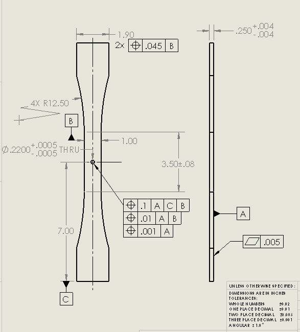
Updated again based on the datum location and tolerance refinement, which I assume is what Powerhound was referring to?

Hopefully I am starting to get this down better :/.

GDTUpdate3_r4aodn.png
 
Just another update in case anyone finds this thread later on.

GDTUpdate4_flhujv.png
 
The little suction cup for B is supposed to be on the surface and the handle of the plunger aligned with the dimension it applies to. I would also suggest adding a diameter symbol to the position controls; since it is one hole the last tolerance of position to A is likely to be argued should be a perpendicularity.

Also, don't align datum C with the 7.00 dimension; it makes it looks like the dimension is for a datum reference.
 
Status
Not open for further replies.

Part and Inventory Search

Sponsor