Continue to Site

Eng-Tips is the largest engineering community on the Internet

Intelligent Work Forums for Engineering Professionals

  • Congratulations cowski on being selected by the Eng-Tips community for having the most helpful posts in the forums last week. Way to Go!

One way slab with transfer loads

Status
Not open for further replies.

Thomas2121

Structural
Jul 17, 2021
8
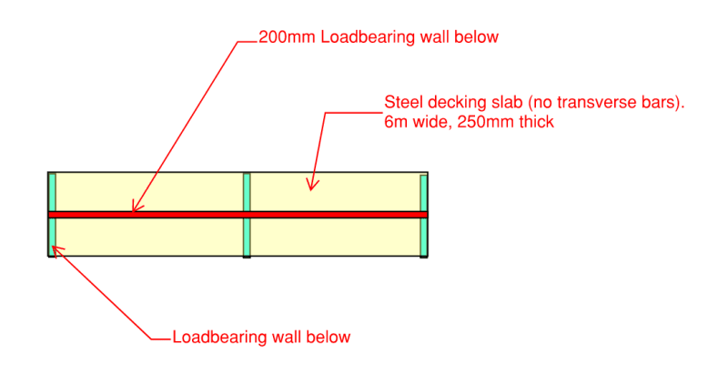
I have this 6m bondek slab that needs to design to take transfer line load along its span.
I am wondering for both strength and deflection check what width do I need to take for where transfer load is and why?

I have used FEA for this full model and the results differ so much compared to my hand cal using one-way slab with say 1m width. And I guess the reason is because the stiffness in another direction is considered. ie the transfer loads is distributed in both X and Y direction, the whole slab will take the transfer load nearly equally. After I change the stiffness in Y direction to near 0 the result is close to my hand cal.
So now my question is, since I don't have transverse bars in the slab. does that mean I cannot use the stiffness in Y direction to distribute the loads? In another word, I can't treat it like a two-way slab right? If the answer is no then back to my first question, what width should I take for one-way slab analysis?

What if I place bars on top of the deck? Do you design steel decking slab as two-way?

hank you.

1_ztdtfv.png
 
Replies continue below

Recommended for you

I'm guessing that the wall shown in red is above the slab, rather than below as noted.

You have two spans, how long are the spans? If your sketch is reasonably to scale, and the slab is 6m wide, then the span looks to be at least 12m. A 250 slab is not going to span that far. But good news, the wall itself should work as a deep beam, provided it is connected appropriately top and bottom.
 
Yeah you are right the red one is the wall above. It’s actually two timber stud walls not RC wall.
The picture is just indicative. The span is 6m roughly.
I am more interested in knowing what width should I take as one way slab or whether I can distribute the transfer loads to the entire slab by adding transverse reo on top of deck to make it two way?
 
The Steel Deck Institute has some methods for calculating effective width of concentrated loads. ANSI/SDI C-2017 would be a good place to start.
 
Thank you. I will have a look.

Will you place transverse bars above the deck to make it two way?
 
Here's a recorded webinar covering the topic:
The slides from the webinar:

There is a worked example for a continuous wall bearing on slab parallel to the decking on pg. 6-23 of the SDI Floor Deck Design Manual (2nd Edition). In the example they check transverse (weak axis of the deck) bending using the WWF temperature and shrinkage reinforcement in the slab as the transverse load distribution reinforcement. The WWF provided sufficient tensile reinforcement for the example, but if your situation required more reinforcement, adding transverse bars would be appropriate.

Relevant excerpts from ANSI/SDI C-2017:

Screenshot_2021-07-18_110922_jvuzma.png


Screenshot_2021-07-18_111038_fgu6en.png
 
Can you not sling a beam in under or design your new stud wall as a truss to span the distance? Without transverse rebar you’ve no reason to take a 1m wide strip. At best you’re getting 45deg each side of the stud.
 
The stud wall will be normal timber wall instead of truss.
Understand that without transverse bars I cannot take the strip width to be 1m. But if I provide full width transverse bars, won't the strip be wider than 1m? I will expect it like a two way slab then : the loads goes to the middle strip and transfer to to the end strip by transverse bars so the load will be distributed to the entire 6m wide slab instead of 1m only?
 
OP said:
the loads goes to the middle strip and transfer to to the end strip by transverse bars so the load will be distributed to the entire 6m wide slab instead of 1m only?
It is unlikely that the load will distribute to the whole width of the slab. 45° seems like a reasonable assumption, but other values may be used. For distribution to large widths I prefer solutions with some vertical reinforcement.
You seem to be asking about a two way slab solution a lot, but I don't see any supports in the other direction.
I usually always put 20% of reinforcement in the other direction and that is required by some of the codes.

In this case I would say that reinforcement in the other direction is important as can be seen on a picture in few post above mine (just think about where the tension will be if you distribute the load).

I don't know much about wood but maybe if this is a wall without openings it can be lifted from the slab so that it acts as a deep beam and has supports only above the walls. There is always several layers of isolation on the concrete slab so wall would seem to the user as supported on the slab, but would actually be spanning independently.
 
If the wall can't span from support to support, I would put in transverse reinforcement for the known concentrated load.
 
Status
Not open for further replies.

Part and Inventory Search

Sponsor