humanengr
Structural
- Aug 1, 2008
- 140
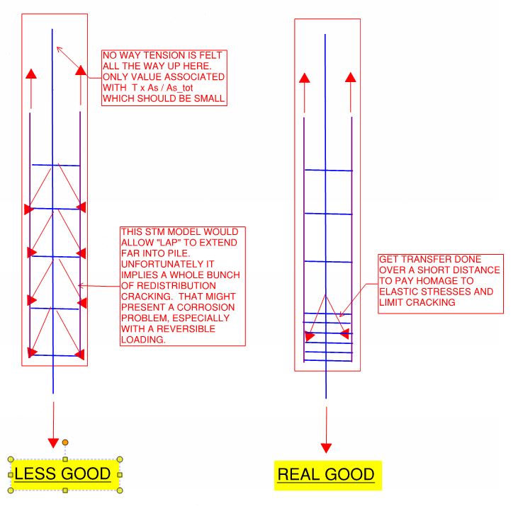
I have a case where tension in the ACIP pile must be transferred from the rebar cage to a center bar which
continues to the bottom of the pile. The rebar cage terminates approximately half way down the length of the pile.
The spacing between the cage rebar and the center bar exceeds 6in. (exceeds maximum for non-contact lap splice).
Since there is a considerable over-lap between the cage and the center bar (approx. 46 ft.), my thought is a combination
of shear stress and diagonal shear or diagonal tension will occur between the outer bars and the center bar. The interface
for these stresses will be approximately at the surface of concrete bonded to the bars.
Due to the large over-lap length, the tension load transfer (and therefore, the shear stress) will be spread out
over a long enough length so as not to exceed permissible stresses.
I would like to avoid extending the center bar into the pile cap - otherwise, the center bar tension would be applied directly.
There is also a theory "out there" that concrete between the bars will be in compression rather than tension, in which
case the distance between non-contact lap splices could exceed 6 in. (2nd sketch).
Just wondering if anyone has a critique of this approach or any comments.
thanks.
![[idea]](/data/assets/smilies/idea.gif "[idea] [idea]")
![[r2d2]](/data/assets/smilies/r2d2.gif "[r2d2] [r2d2]")