SouthPark
Electrical
- Jun 28, 2018
- 2
Hi all.
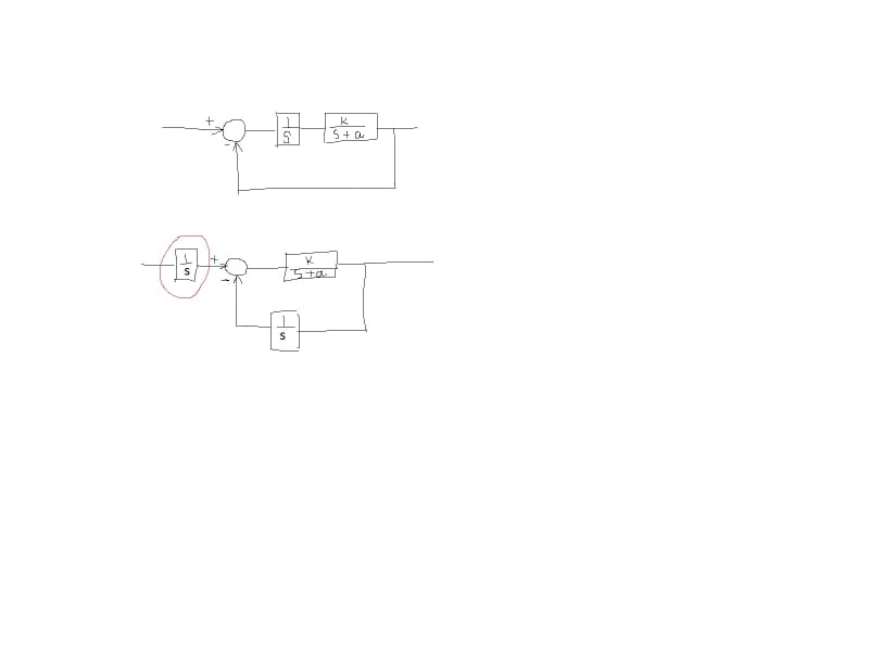
From automatic control theory involving Laplace blocks, I can see that the two systems (drawn in the figure) are 'equivalent'.
However, the lower figure with the pure integrator at the input becomes a practical problem, or something that is not practical or workable, right? My thinking is that the 1/s block is a pure integrator, so if the input signal is a constant value, then the output of the integrator just keeps getting larger and larger indefinitely, right? So if this were to be done with a real-world system, then this wouldn't work, right? Thanks all!