Continue to Site

Eng-Tips is the largest engineering community on the Internet

Intelligent Work Forums for Engineering Professionals

  • Congratulations cowski on being selected by the Eng-Tips community for having the most helpful posts in the forums last week. Way to Go!

identifying an involute spline 1

Status
Not open for further replies.

JEMMERICH

Mechanical
Oct 15, 2007
22
I am reverse engineering an internal involute spline and I am unsure what it is, it doesn't seem to be a DIN or ANSI design.
I believe it may be JIS?? It is a Komatsu part. My first question is: Is there a way to quickly identify a spline dp/MOD and pressure angle similar to identifying a gear using base pitch?

anyhow this is what i have
internal tooth
minor diameter: 45.00mm
major diameter: 50.00mm
1.546" across .2057" pins

any ideas?

Thanks, John
 
Replies continue below

Recommended for you

Working out the base pitch is always the best way to start.
From there; you need to be able to reference all the standards to correctly identity a spline.

How many teeth are in your example?
Is the profile flat root or fillet root?
 
Jemmerich

are trying reverse engineer to mfg 1 part or thousands of parts.
if it is a off the shelve item it would be cheaper to buy it.


the base pitch like gearcutter said it is a good place to start, but
to be absolutely right you need to have it reversed engineer inspected by a gear shop.
that has an unknown gear program on a CNC gear inspection system. or minimum an involute
inspection machine. if you have the correct diametrical pitch or mod and pressure angle.
then the involute verification will be correct.
it will remove all doubt.

Mfgenggear
 
Sorry, I forgot it is 18 tooth.
So base pitch does work on splines, good to know.
As far as referencing all the standards, I looked at the din and ansi stuff but the JIS stuff is not easy to read in japanese
 
JIS Standards that have been translated into English are available.
I have the JIS 20deg PA & 30deg PA standards and they are both in English.

You haven't answered my question - Is the profile flat root or fillet root?

Both DIN5480 & JIS show the internal major & minor diameters that you've quoted for 2.5 module/18 teeth, but don't match the size between pins.
Both standards are showing 5mm (0.1968") as being the optimum pin size for that pitch.
You may need to flatten the pins slightly.

What condition is the sample spline in?
Is there any wear on either the flanks or diameters?
Do you know what the base pitch is?
Do you know what the major diameter of the shaft is?
Do you know if the external teeth have tooth tip chamfering?
 
Geez my head has been spinning lately,

It is a flat root.

Luckily I have .1968" measuring wires, and like you said they needed some grinding to avoid hitting the root.
I measured 1.580" between pins.
The spline is brand new, never used, no wear at all.
I do not have the mating shaft nor do I have any information on it other than it is a pinion gear like what you would find in the rear end of a rear drive automobile.

 
 http://files.engineering.com/getfile.aspx?folder=d89d4316-c201-4d5f-ae34-cbb69773db98&file=unnamed.jpg
You have a very specialised spline there.
It will be difficult for you to have these made in small quantities.
JIS major diameter fit splines are usually broached due to the tight tolerance given to the internal major diameter.
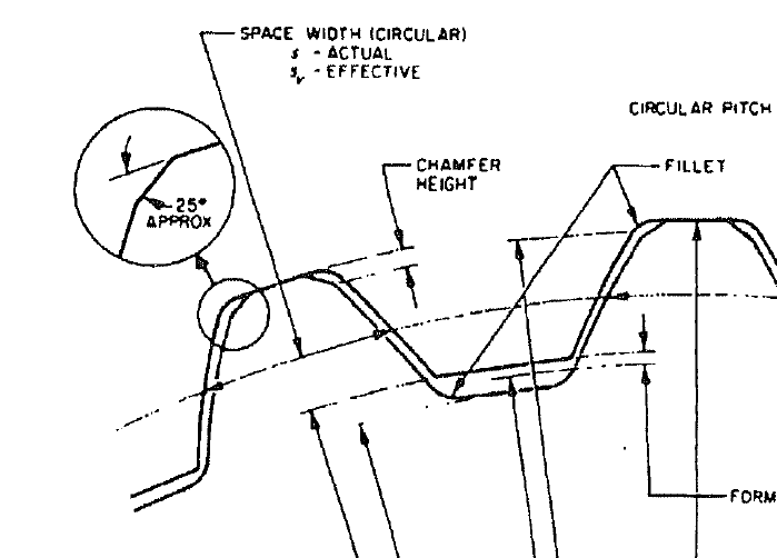
The tooth tips on the shaft will need to be chamfered otherwise they will interfere with the corner root radii of the internal.
For small quantities; I would recommend you get these EDM wire cut.

JIS-D-2001, 2.5 module
20 degrees Generating Pressure Angle
Major Diameter Fit

Z = 18
x = 0.8
Nominal Diameter = 50.00
Standard Pitch Diameter = 45.00
Major Diameter = 50.00 R7 ( +0.000 / -0.025, -0.050 )
Minor Diameter = 45.00 H7 ( +0.025 / -0.000 )
Measurement Between 5.00mm Pins = 40.168 ( +0.085 / -0.000 )

All dimensions are in metric.


gearcutter- nice work!

JEMMERICH- Attached is an example of the type of tooth tip chamfer recommended with major diameter fit splines. You need to be careful with dimensions/tolerances of these tip chamfers. On one hand, you want the chamfer large enough to ensure the tip corners never bear against the fillet surface. But you also don't want to make the chamfers so large that there is insufficient area left at the tooth top land where it contacts the root surface. Looking at your picture of the internal spline it appears the root fillets have a very small radius, so this should not present an issue.

You mentioned you don't have the mating component or know what the external spline looks like. Due to the close tolerance fit between the external spline tooth tips and the internal spline roots, you need to be careful about the axial length of contact at the tooth tips/roots. It is quite easy to create excessive interference with long contact lengths. With major diameter fit splines that are required to slide and also require long engaged lengths to handle torque, you can relieve the top lands at each end of the external spline so that there is just enough area left at the center to support/position the mating parts.

maj_dia_fit_spline_edge_break_wsmvnx.png
 
Status
Not open for further replies.

Part and Inventory Search

Sponsor