Continue to Site

Eng-Tips is the largest engineering community on the Internet

Intelligent Work Forums for Engineering Professionals

  • Congratulations cowski on being selected by the Eng-Tips community for having the most helpful posts in the forums last week. Way to Go!

How to read "Means this"?

Status
Not open for further replies.

SeasonLee

Mechanical
Sep 15, 2008
918
Hi All

Please ref to Fig. 12-2 of Y14.5-2018 as shown below
2020-07-09_130321_lnvaxb.jpg

2020-07-09_130118_chc5tk.jpg


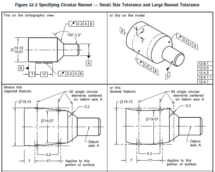
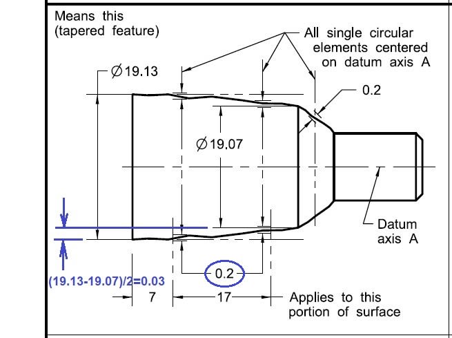
I have a question at "Means this", how can a 0.2 tolerance floating within a 0.03 tolerance zone? Please let me know if anything I missed here. Thanks for your help.

Season
 
Replies continue below

Recommended for you

That's what you get when using a drawing program that is not to scale combined with rushing the process under the radar.
 
SeasonLee,

Would a three lobed shape accomplish this?

Maybe they did not do the arithmetic.

--
JHG
 
Season,

Good catch, I'd say that figure (at least not the tapered/bowed sections) does not represent what is happening very well. I don't see any way a runout tolerance greater than the size tolerance could control variations in form for a feature subject to rule #1 (at least if we consider form variations alone - combined form/orientation/location deviation would be a different case). If rule #1 did not apply then perhaps the "bowed" case would be applicable, but still not the "tapered" case.

Its actually right there in the accompanying text. They probably should have only included the tilted/eccentric cases.

Y14.5-2018 para 12.5.3 said:
When a circular or total runout tolerance is larger than the size tolerance, the size tolerance controls variations in size and form. The larger runout tolerance controls the orientation and coaxiality to the datum axis for a surface of revolution.
 
hey guys I don't know much
but my analysis is this:
the diameter size is independent of the runout.
the 19.13 diameter has to be in size, how ever it can have eccentricity to datum -B- of .2 runout.
other words clamp -B- in a v block or a chuck. spin it, and an indicator is placed over the 19.3 diameter,
the runout has to be with in .2
and this can very well happen. even if it's sloppy work.
 
Thanks for all you guys comments.

mfgenggear said:
how ever it can have eccentricity to datum -B- of .2 runout

The indicator reading can be equal to 0.2 max, but the eccentricity(or offset) can not be larger than 0.1, since the max axis offset permissible between the datum axis(datum A instaed of datum B) and the toleranced feature is only one-half of the runout tolerance value.

There are few examples in the standard with large size tolerance and small runout tolerance, like Fig.12-7, this can be easily visualized, but its really hard to image the case with small size tolerance and large runout tolerance. May I understand this way:
Rule #1 applied, each circular element must be within size limit.
The worst case boundary is 19.33(= 19.13 + 0.2) wrt datum A|B

Season
 
@season lee
yes the runout from center line is .1 however total indicator runout movement is .2
I have check a million parts this way in my past life.
go to the inspection floor, find a similar part and verify this for your self.
 
Image upload requires a number of scripts and doesn't work for PDF. Not knowing you setup or what file type you were uploading, it's tough to determine the cause. .PNG would be my first choice. I think mathjax and cloudflare need to be allowed.
 
The OS is less important than the browser settings. .JPG is designed for continuous tone images; .PNG is better suited for line art and text.
 
Ya I will figure it out, security settings are blocking the upload , thanks 3DDave
 
@mfgenggear
When verifying runout, the dial indicator reading includes several types of part errors: form, orientation and location(axis offset). Your figure shown is an error of axis offset, my question is on the form error, how to interpret the "Means this"? how can a 0.2 tolerance floating within a 0.03 tolerance zone? The figure shown on the "Means this" is not easily visualized for me. Anyway, thanks for the picture posted.

Season
 
Season Lee,
The figure you posted shows clearly that the form error is limited within the 0.06 size tolerance. The 0.2 tolerance of runout is unable to control form because it allows more form error than available per rule#1, So it limits orientation and out-of coaxiality.
The fact that 0.2 tolerance is shown larger than half the size tolerance is just a technical problem with the graphic.
 
Burunduk said:
it allows more form error than available per rule#1
The more form error is limited by the worst case boundary 19.33, am I right?

Season
 
If rule #1 would not apply and the entire runout error was the result of form variation (no axis offset and no orientation error of the UAME), then yes, this is the worst-case boundary that would limit the form variation.
 
@mfgenggear
When verifying runout, the dial indicator reading includes several types of part errors: form, orientation and location(axis offset). Your figure shown is an error of axis offset, my question is on the form error, how to interpret the "Means this"? how can a 0.2 tolerance floating within a 0.03 tolerance zone? The figure shown on the "Means this" is not easily visualized for me. Anyway, thanks for the picture posted.

@season lee
@Brurunduk has clearly answered the question, however I will give my answer in laymen terms.
in order meet the requirement if the two diameters were in theory perfect cylindrical diameters the full runout could be utilized.
being this is not a perfect world and there are errors in the roundness and taper, now the runout has to be held tighter.
so other words all inclusive. from the theoretical these are maximum allowable errors, in the real world
the machinist has tricks up his sleeve. he would turn these diameter to obtain the designers requirements.
he or she would hold the diameters with the least amount of errors. but take into account he can & will use the maximum tolerance allowable.

even thou the authors never provide manufacturing centers it is a common mfg method for cylindrical parts with tight total runout
and runout, pretend that the " mean this " had centers it is now easier to verify runout on both diameters for manufacturing and inspection.
held between centers, my reason or rational for specifying about centers is this.
in a perfect world datum -A- would have zero runout, but as know that is not possible. if the run out of a is .1 total runout, then the 19.3 dia diameter has to be
held w/I .1 to obtain the designers requirement. as draw there nothing wrong with "Mean This" but to give an other perspective.
so no matter of the form variation as Bunrundak nicely pointed out. as the form varies, the run out still has to be in tolerance.
 
Status
Not open for further replies.

Part and Inventory Search

Sponsor