Continue to Site

Eng-Tips is the largest engineering community on the Internet

Intelligent Work Forums for Engineering Professionals

  • Congratulations cowski on being selected by the Eng-Tips community for having the most helpful posts in the forums last week. Way to Go!

How do I analyze the forces and reactions of this frame?

Status
Not open for further replies.

Pororo

Civil/Environmental
Mar 1, 2018
18
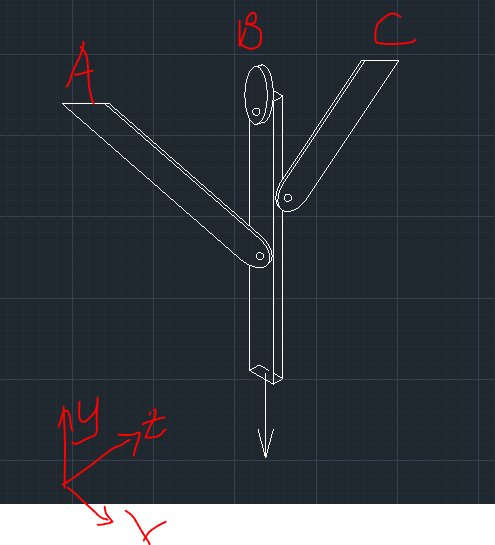
Here is the drawing for the structure. Basically, it concerns 3 dimensions,. The structure is supporting a weight indicated by the arrow pointing down. All of the 3 supports at the top are pin-supported (to my understanding. That support drawn at B is same for A and C). To my understanding: I have 3 reactions per support, Rx, Ry and Rz so a total of 9 reactions. Maz = 0, Mbz = 0, Mcx = 0, ΣFx =0, ΣFy = 0, ΣFz = 0. Am I on the right path in the analysis of this one? If so, since the indeterminacy is 3 degrees, what additional equations can I use to solve the indeterminacy? Thanks!

Drawing_ay20ol.png
 
Replies continue below

Recommended for you

Unless you have lateral loads to consider (e.g. seismic potential):

Consider the stiffness and tolerances of the connections to members A&C to be relatively low, therefore B carries all of the weight. Done.

If there are lateral loads:

If we assume that members A and C are bar-like and pinned in perpendicular planes per your sketch, consider them effective in only the one plane each. I presume you intend to show the B support as some sort of pin (in both directions?). In that case, the problem becomes either determinate or nearly so (depending on the bending stiffness of member B), and can be solved by hand methods. Compatibility of deformations (unit load) would be one such method.

----
just call me Lo.
 
There is nothing to be gained by performing an exact analysis. Member B is carrying all of the load below the intersection of A and B, so members A and C are redundant and may be considered lateral braces. Any tension they may carry would be a secondary effect.

BA
 
Unless this is some exercise for a structural analysis college class - all the load goes to the central member!

As pointed out above, the central member has to take 100% of the tensile force below the points where A and C connect, so anything beyond this simplistic analysis is redundant in any event.
 
As Lo said, no lateral load = no load in A or C.


Rod Smith, P.E.
 
HotRod10 said:
As Lo said, no lateral load = no load in A or C.

To be more precise, no lateral load = very small load in A or C. Members A and C must take some tension but it is a secondary effect caused by the strain in member B.

BA
 
BAretired said:
Members A and C must take some tension but it is a secondary effect caused by the strain in member B.

I guess theoretically there would a tiny amount of tension in A and C. However, unless the vertical member is restrained from lateral movement, it would be an infinitesimally small portion of the load.


Rod Smith, P.E.
 
Status
Not open for further replies.

Part and Inventory Search

Sponsor