Continue to Site

Eng-Tips is the largest engineering community on the Internet

Intelligent Work Forums for Engineering Professionals

  • Congratulations cowski on being selected by the Eng-Tips community for having the most helpful posts in the forums last week. Way to Go!

Dynamic Profile Modifier questions 2

Status
Not open for further replies.

SeasonLee

Mechanical
Sep 15, 2008
918
Hello All

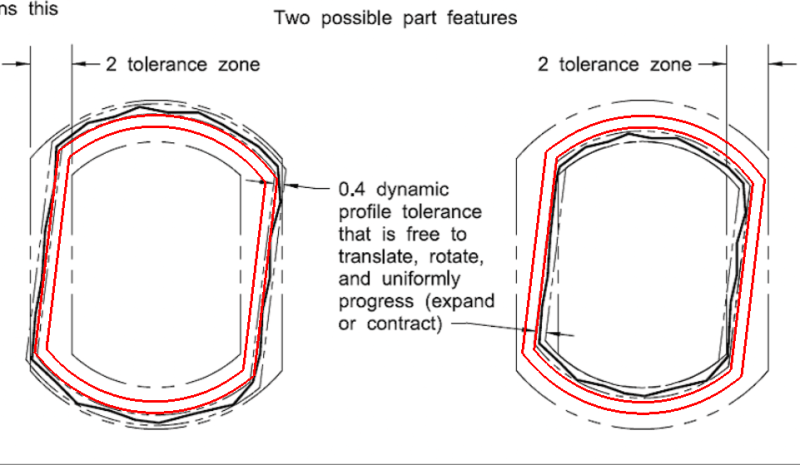
Please ref to the snap shot below, this is from Y14.5-2018 Figure 11-35, I'm interested to know what will be the differences by removing the Dynamic Profile Modifier from the lower segment.

Dynamic_profile_modifier_Question_oj6dqa.jpg

Thanks in advance

Season
 
Replies continue below

Recommended for you

SeasonLee,

If you remove the dynamic modifier the 0.4 wide tolerance zone will not be able to expand/contract as shown. A 0.4 wide profile zone equally disposed about the true profile on the print defined with basic dimensions will be able to only shift (rotate/translate) within the upper segment 2.0 wide tolerance zone.

Edit: For example - neither of the two variations in the "means this" section of 11-35 would be possible without the dynamic modifier. The one on the left represents expansion and the one on the right represents contraction (as well as of course rotation/translation in both cases).
 
Chez311,

Would you use dynamic profile modifier for a nominally planar surface?

If a slot is dimensioned / LOCATED from its side (and not from the middle plane of the slot) with profile (lets say .050 to a datum reference frame) and the size of the slot is within ±.010, could this scheme be valid without the dynamic profile shown on the profile (again to locate one side of the slot)?

 
Kedu said:
Would you use dynamic profile modifier for a nominally planar surface?

The concept and purpose of Dynamic Profile Modifier is to divorce the control of form and size, and a planar surface normally without any size on it, so this midifier will use for an irregular-shaped opening or irregular external shape, and it will not applicable to a planar surface. Dynamic Profile Modifier will control or define on features with complex and unusual shapes, normally it will accompany with ALL AROUND or ALL OVER symbols on the applications.

Although the Dynamic Profile Modifier is not applicable to a planar surface, but it can be applied to a surface of revolution as shown on Figure 11-38(2018 version).

I would like to hear the comments from others on your 2nd question.

Season
 
Hi All,

I agree with chez311's explanation of what would happen if the dynamic profile modifier was not present. The zones would not be able to expand or contract (progress, as Y14.5 describes it) to accommodate the "size" variation of the feature. Here is what the non-progressed zones would look like:

Fig_11-35_means_this_with_non-progressed_zones_swduld.png


Evan Janeshewski

Axymetrix Quality Engineering Inc.
 
Kedu,
I think your question is a good one as it brings up some gaps in our understanding of how exactly the dynamic profile modifier behaves. While I don't think a single planar surface is the best application of the modifier as there are other established ways to accomplish the behavior you describe (progression of a single planar surface) I'm not going to say it can't be done as its not prohibited. The same goes for any discontinuous surface -especially those lacking 180deg points- controlled with dynamic profile. I would like to see a solid mathematical definition of dynamic profile, however considering Y14.5.1-20xx will only be fully compliant to Y14.5-2009 and I don't remember anything in the draft relating to this I don't see that happening anytime soon unfortunately.

Evan,
Have you seen any attempt at a mathematical definition of dynamic profile? I know the term "size" gets thrown around quite a bit but the only way I know of to concretely define "size" is per the swept spheres interpretation however I believe this is only indirectly controlled by profile (or not defined for non-FOS) - conversely the other controls form, location, and orientation are all directly controlled. I have a hunch that the behavior allowed (namely the progression of the tolerance zone) by dynamic profile needs a separate definition as well as how exactly it behaves in relation to the DRF by constrained DOF (namely translation).
 
Just to throw it out there - if we take the "size" variation allowed by the dynamic profile as suggested by 11.10 to mean something along the lines of "uniform progression of the tolerance zone normal to the true profile while maintaining a constant width" - uniform progression being that the normal (perpendicular) linear distance from all points on the true profile to the tolerance zone changes at an equal ratio - then I don't see any reason why dynamic profile should be limited to all-around or "closed" features. This could be anything from a single planar surface, an arc having less than 180deg points, or any imaginable shape.

DOF constraint, specifically translation to a dynamically changing tolerance zone, seemed a little more nuanced but now that I think about it all DOF constraint could be applied to the true profile (which never changes - I think?) and the tolerance zone is allowed to progress relative to the constrained true profile.

Evan, and others, any thoughts?
 
kedu said:
If a slot is dimensioned / LOCATED from its side (and not from the middle plane of the slot) with profile (lets say .050 to a datum reference frame) and the size of the slot is within ±.010, could this scheme be valid without the dynamic profile shown on the profile (again to locate one side of the slot)?

Chez311,
Would you think this combination is valid?
Why would you dimension only one side of the slot (or tab for that matter) with profile and with ± the size of the slot/tab instead of using position for the middle plane of the slot?

 
greenimi,

My above comments (28 Oct 19 19:51) and (29 Oct 19 15:04) were more in relation to the mechanics of how dynamic tolerance works as well as applying it to planar or open (as opposed to closed) features. They weren't really addressing that part of Kedu's question, it seems to me Kedu was proposing the +/- scheme instead of dynamic profile applied to a planar surface.

That said, if using a standard profile tolerance (NOT dynamic profile) I don't see why it wouldn't be valid. Replace Y14.5-2018 11-32 (or Y14.5-2009 fig 8-27) with profile of a surface instead of a line. As to why one would use that instead of another method, I don't know I didn't propose it.
 
chez311 said:
That said, if using a standard profile tolerance (NOT dynamic profile) I don't see why it wouldn't be valid. Replace Y14.5-2018 11-32 (or Y14.5-2009 fig 8-27) with profile of a surface instead of a line. As to why one would use that instead of another method, I don't know I didn't propose it.

UUPPSS!! Wrong guy. I meant the post to be addressed to kedu............
Interesting enough I quoted kedu, but asked chez311 for additional info.....hmmmmmmm


Evan, and others, any thoughts?

I agree with this assessment.

Of course the standard has a much longer and more complicated explanation, but here's how I'd put it:

A dynamic profile tolerance requires that the actual surface fall between two boundaries, each of which has a uniform offset from the true profile. The separation between the two boundaries is equal to the tolerance value.​

This is basically a generalization of total runout.


pylfrm
 
Will somebody educate me please.
As dynamic profile "progresses" away from true profile, should it:
a) maintain the ratio between the features (in case of Fig.11-35 3:4 between the width and diameter), or
b) maintain uniform offset from the true profile,
because you cannot have both at the same time.

If my question sounds confusing, just pick one:

Capture_jhcaon.png


"For every expert there is an equal and opposite expert"
Arthur C. Clarke Profiles of the future
 
I am learning this stuff now, but for the sake of discussion and with its applicable risk I would go and choose b.)
I also found this article (not remember if I got it from this forum or from other ones)


Dynamic profile is detailed a little bit with some extra examples.
 
CH,

I presume your question about ratio is in relation to my post (29 Oct 19 15:04). I am not proposing your example (a) to "maintain the ratio between the features" but instead change maintain the ratio between the normal distance from the true profile to the tolerance zone at all points by the same amount*. My purpose in this statement was to not exclude the use of dynamic profile modifier on nonuniform profile tolerances like Y14.5-2018 fig 11-11 to 11-14 which do not have a "uniform offset" to the true profile.

I guess if the word ratio is a sticking point one could use either version of my statement from the referenced post:

"uniform progression being that the normal (perpendicular) linear distance from all points on the true profile to the tolerance zone changes at an equal ratio"

OR


*I would change my statement to the below:

"uniform progression being that the normal (perpendicular) linear distance from all points on the true profile to the tolerance zone changes by the same amount"

*Edit - I retract my statements about ratio. My intent remains the same but I realize that the ratio is not what needs to remain the same, but the difference between the distances.
 
Note my edits to my post (30 Oct 19 12:32). It appears I should not have referred to the ratio at all, thank you CH for pointing that out - while your (a) was still not what I was proposing, my inclusion of the term "ratio" was I think incorrect. What I instead wanted to maintain was the amount the normal distance changes at all points instead of a "uniform offset" which would assume a uniform normal distance (ie: uniform profile tolerance).


pylfrm,
See the above - I was avoiding the term "uniform offset" and it seems I may have missed the mark slightly in my first attempt. Hopefully my revisions make sense, I was trying to come up with a general solution which didn't exclude non-uniform profiles.
 
Thank you greenimi and chez,
I was not trying to pick on particular post.
I don't have a copy of the standard; I think the answer to OP's and other questions is in robust mathematical definition of "progressing"
The dynamic tolerance zone is clearly not created around true profile as we are used to, but around something else.
How this "something else" is generated in relation to true profile still a bit murky, hence the question.

"For every expert there is an equal and opposite expert"
Arthur C. Clarke Profiles of the future

 
CH,

I see - I assumed you were referring to mine since the standard does not refer to ratio, apparently for good reason. I agree a robust mathematical definition would be ideal though I wouldn't hold my breath for one from the committee (having thought about it - seems a bit backwards to me, to introduce the concepts first and then figure out the math later). That said, I am pretty satisfied with the clarification arrived at here, not that it offers much beyond what the standard provides but at least I feel I can apply a bit more rigor to the concept.

The dynamic tolerance zone is clearly not created around true profile as we are used to, but around something else.

Why not? The uniform progression would take place relative to the true profile, additionally per my (29 Oct 19 15:04) I was thinking that DOF constraint relative to the DRF could be applied to the true profile instead of the progressed tolerance zone.
 
This is how ISO deals with the concept.

capture2_gadobv.jpg


I believe it would be much easier for everybody if Y14.5 explained their dynamic profile modifier in a similar fashion.
 
Pmarc,
Don't you think ASME is written in more legalistic way ?

Or in other words in a language that almost all the time needs "translation" and the training companies can make money of? Follow the money so to speak...
Not that ISO does not have their own problwms (like you said configuration management), but I think is written in a "down to the earth" language, better explanations.....
 
pmarc,

If I understand the figure correctly, going by the key, I believe that (1) the TEF would be equivalent to the "true profile" and (r) the constant unspecified offset would be essentially what I was trying to express as the "normal linear distance changing by the same amount".

If so I guess (5) the circles/spheres defining the tolerance zones along the offset reference feature could be defined as either all having the same diameter (uniform tolerance zone) or varying diameter (non-uniform tolerance zone) which would be the general case I was after. Definitely a more concise and well defined way to describe the same concept.

It seems to me that in both cases any DOF constraint to the DRF should still be applied to the feature of fixed and theoretically exact "size" and form - ie: the TEF (for ISO) or true profile (for ASME). Effective constraint and behavior of the tolerance zone would be an indirect result of directly constraining the TEF/true profile.
 
Status
Not open for further replies.

Part and Inventory Search

Sponsor