lucky-guesser
Industrial
- Apr 11, 2023
- 137
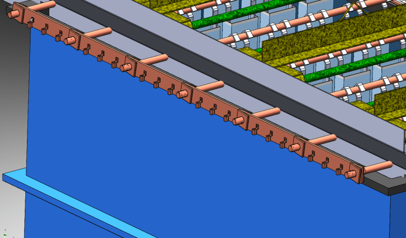
Hello all, I am designing the copper bussing (see attached concept image) for a new zinc plating tank to be built by an outside supplier who specializes in tank building. We are trying to minimize cost as much as we can so we are building the tank to have more electrical capacity than we should actually need but we don't want to overbuild more than necessary, copper is expensive and we are already over budget. The issue I'm having with the tank company is a disagreement over the size of the bus bar that ties our anodes together.
Our current tank is rated for 1500 amps, and the current bus bar is 1/4 x 2, and using the traditional wisdom of 1000amp/in^2, that would mean that this bar is only good for 500 amps. The reason we can get away with this (in my opinion) is because we have 18 wires spread across this bar, going to 7 different anodes, so the amperage is spread out and no one cross section actually sees that full 1500 amps. We have had no heat issues in the past, I would say the current bar is very close to if not room temp, so there is no build up.
We are building the new tank to be good up to 2000 amps, and what the manufacturer is wanting us to do is use a 1/2x4 bar (2000amp). I have the new bus bar drawn up as 3/8x3 (1,125 amp) which should already be scaled up more than enough for no more than we are increasing the tank rating.
Question is, is there some obscure electrical property that I am unaware of that would cause the bus bar to actually see full load at a given point? I wouldn't think so considering how small our current one is that hasn't caused any issues but with how much push back we are getting I figured I should do some investigating. Our current design is fairly unorthodox compared to the designs that this company usually works with so I am thinking that they may just be stuck in the mindset they usually have where the full load is coming in from one end and not distributed like in our case.