TEguy
Mechanical
- Aug 21, 2007
- 9
This question was asked in an similar thread (thread406-36822) which is now closed.
The question was:
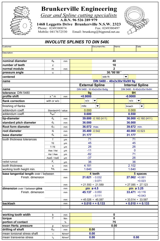
Are there any rules to determine exactly when to apply addendum modification to a DIN 5440 involute spline? How is the amount of modification determined? Is this normally given on the drawing as part of the spline spec.?
The answer by gearguru was:
the DIN splines use the profile shift for achieving the proper standardized main dimensions. One of them is the OD - the DIN standard splines allways create a small clearance for sliding - say - a standard ball bearing above them. Therefore the shift is different for differenf modules and OD's. I have a copy of DIN spline standard, please post here more data about your spline, I can help you to find more. By the way - DIN includes charts with ALL dimensions of the (finished) spline, you do not need to calculate anything unless you want to.
So I am having the same issue as the originator of this thread.
We have purchased a hydraulic motor from a reputable manufacturer, the motor shaft is specified as W40x2x18x9g.
We need to manufacture a hub to fit on this shaft.
The only information we have about the shaft spline is W40x2x18x9g.
How can we tell from this if any addendum modification was used in the calculation of tip circle diameter and root circle diameter?
This will determine the calculation for the diameters of out hub will it not?
All help is appreciated.
Regards
TEguy
The question was:
Are there any rules to determine exactly when to apply addendum modification to a DIN 5440 involute spline? How is the amount of modification determined? Is this normally given on the drawing as part of the spline spec.?
The answer by gearguru was:
the DIN splines use the profile shift for achieving the proper standardized main dimensions. One of them is the OD - the DIN standard splines allways create a small clearance for sliding - say - a standard ball bearing above them. Therefore the shift is different for differenf modules and OD's. I have a copy of DIN spline standard, please post here more data about your spline, I can help you to find more. By the way - DIN includes charts with ALL dimensions of the (finished) spline, you do not need to calculate anything unless you want to.
So I am having the same issue as the originator of this thread.
We have purchased a hydraulic motor from a reputable manufacturer, the motor shaft is specified as W40x2x18x9g.
We need to manufacture a hub to fit on this shaft.
The only information we have about the shaft spline is W40x2x18x9g.
How can we tell from this if any addendum modification was used in the calculation of tip circle diameter and root circle diameter?
This will determine the calculation for the diameters of out hub will it not?
All help is appreciated.
Regards
TEguy
![[upsidedown]](/data/assets/smilies/upsidedown.gif "[upsidedown] [upsidedown]")