Diametrix
Aerospace
- Jan 31, 2023
- 50
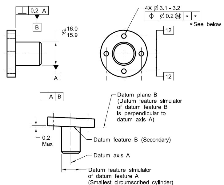
One thing I'm still struggling to understand is what is the difference between specifying a single cylindrical feature datum for true position tolerance or the same with a flat perpendicular surface used as the secondary datum when no material boundary modifiers are used. Here is an example from the standard:

Here we have true position tolerance zones for the four holes as four cylinders which axes are basically located and parallel to the datum axis A which is the axis of a smallest circumscribed cylinder that is touching the datum feature B. I guess my problem in understanding is right here - why is it important that it is making contact with the datum feature B? If we remove datum B completely from the FCF and have only datum A referenced, wouldn't we end up with exactly the same size and orientation for the tolerance zones for those holes?

Here we have true position tolerance zones for the four holes as four cylinders which axes are basically located and parallel to the datum axis A which is the axis of a smallest circumscribed cylinder that is touching the datum feature B. I guess my problem in understanding is right here - why is it important that it is making contact with the datum feature B? If we remove datum B completely from the FCF and have only datum A referenced, wouldn't we end up with exactly the same size and orientation for the tolerance zones for those holes?
