Continue to Site

Eng-Tips is the largest engineering community on the Internet

Intelligent Work Forums for Engineering Professionals

  • Congratulations cowski on being selected by the Eng-Tips community for having the most helpful posts in the forums last week. Way to Go!

Customized DRF Example

Status
Not open for further replies.

pmarc

Mechanical
Sep 2, 2008
3,227
This thread has been inspired by some comments (recent and past) that implied that the usefulness of the customized DRF concept is questionable at best.

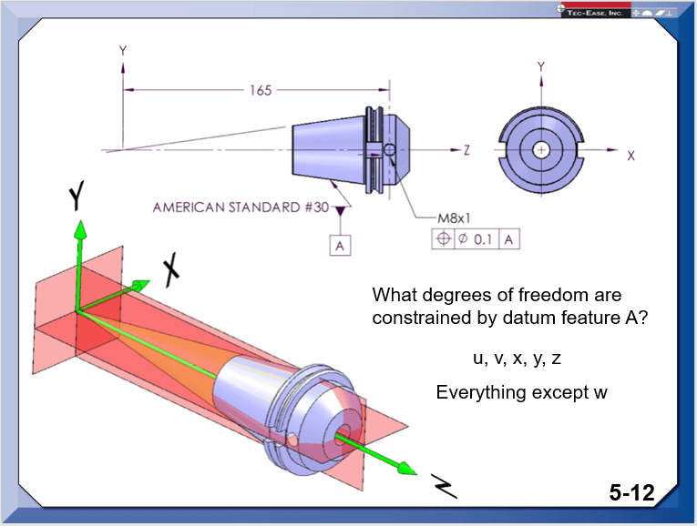
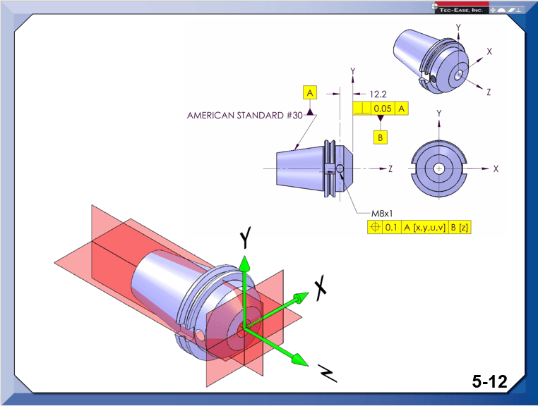
So I would like to ask for opinions about the attached example. Do you think the customized DRF for the pulley (primary conical datum feature constraining 4 and not 5 DOFs, and secondary planar datum feature constraining 1 translational DOF) in this case would not make sense?


Thank you.
 
Replies continue below

Recommended for you

Well Don clearly explains in the video that the origin of measurements moved from the appex of the cone to the surface datum B. That why X, Y and Z intersection is where it is shown in the "big picture" from Season and the "small picture" from John.

3DDave,

3DDave said:
I said the surface used as B needs to be located from the cone vertex
Are you suggesting that the video and side explanation could be wrong or missleading? Just curious.
 
I seriously did not think this would generate as much off topic discussion as it did. I only attached a snip of the point I was trying to convey. I'm attaching two larger snips of the entire slides so everyone can see the context. This is from the section that explains how a customized datum reference frame works and is one of three different examples. The part of the course that explains how to locate all features from a datum reference frame is in previous chapters. These are incomplete drawings so as not to distract from the point being made, much like most every figure you'll find in the standard. The missing diameter symbol is a typo. It's present in the top image. I'll get that fixed. I never noticed it before.

The top image is how the feature has to be checked in the absence of a customized DRF. This is a tool holder so locating the set screw hole is perfectly fine coming from the face instead of the apex of datum A.

The bottom image is showing the customized DRF and how it changes the origin of measurement from A to B. Nothing that is missing from either of these images detracts from the point.

custom_DRF1_dwin4r.png

custom_DRF2_npbopz.png


John Acosta, GDTP Senior Level
Manufacturing Engineering Tech
 
pmarc,

Your example would be more interesting if your pulley were a bevel gear, making axial position critical. Based on ASME Y14.5-2009 section[ ]4.23, the tapered hole positions the pulley and provides all the datums required to inspect the part. The front face is used for clamping and is otherwise, not functionally critical. The hub has a mount face that is critical. This can be positioned accurately from the one and only conical datum, or the cone can be positioned accurately from the primary datum face, and used as a centreing datum. I don't see a benefit to the customized DRF.

Making the inspection tooling for this thing will be fun.

--
JHG
 
greenimi, I see no video. Changing the origin for a subsequent feature does not provide an origin for the precedent features.

ph - there's no tie between being aligned to the axis and being offset along the axis, so a diametral zone is not representative of the mechanical interface between the two.

Before the availability of the custom DRF this would have been accurately represented by using two orthogonal FCFs, one representing the amount of acceptable variation off-axis, a second one representing the amount of acceptable location variation from the face, and a third for the perpendicularity to the axis. Moreover, the bore of the tool holder is what locates the tool and should probably be used as the primary datum.

The use of a custom DRF in this example blurs the separate contributions - the off-axis location may affect balance and clamping ability, while lengthwise location may affect tool resonance/tool chatter, and the perpendicularity affects the uniformity of the clamping action.

It makes sense that those have separate limits/sensitivities that don't happen to be contained in a circle.

I do expect that this analysis is never done, so the most likely outcome is a tolerance that is much tighter than it needs to be in exchange for cargo cult acceptance that since it superficially looks like other cases it should be toleranced like other cases, or the excuse that since one of the characteristics dominates by being such a small tolerance that the others are carried along for free. Neither of which records the actual limits of utility available to a more specific description.
 
Dave, so are you saying this is an incorrect application of a customized DRF because it violates the rules or because you would have done it differently? Maybe I should have used the example in the standard where the actual function of the part isn't known.

John Acosta, GDTP Senior Level
Manufacturing Engineering Tech
 
greenimi,
I'm with 3DDave on this one, however I may look into the premium membership for tec-ease - $50 a year is plenty affordable, I thought it would be much pricier. Thanks for the tip.

3DDave,
For the uninitiated among us (me) could you explain or maybe link to an example of what your orthogonal FCF's (pre-customized DRF) might look like and how the actual control of location/orientation differs from a customized DRF? I think I sort of understand what you're talking about but I can't quite wrap my head around it.

John,
I typically always think of toolholders when I look at the conical example of customized DRF in the standard (4-44 / 4-45) however I'm not sure your example is an ideal utilization of custom DRF. Just to verify, I still assume that any dimensions locating the face that is datum feature B is omitted for clarity, correct? Even if you don't need such a dimension to locate the set screw hole in reference to the customized DRF, you still need to locate datum feature B to A or vice-versa.

That being said, the reason why I don't think its ideal is that the set screw hole really only needs to be held in relation to the front face and central bore where the tool is inserted as 3DDave noted, so for this particular feature a customized DRF is not really necessary. In fact with most standard taper tooling the conical taper constrains all 5 DOF including translation in Z when its mounted in the spindle, so I'm not sure if custom DRF makes sense in most of those cases.

However, one could look to some of the dual contact tooling on the market for examples where a customized DRF might make sense for certain features. I believe the concept here is that the conical tapered portion engages to establish a tool axis coaxial with the spindle axis (4 DOF constrained [x,y,u,v]) - as the drawbar forces the taper together there is combined elastic deformation of the spindle/toolholder until the axial face of the holder is engaged to constrain the final DOF [z]. Now granted this may create some difficulties when taking into account the elastic deformation in inspection (restrained/clamped condition) and I'm not sure exactly how that interplays with the rules (mathematical or otherwise) of customized DRF however in order to properly account for real world assembly/interface conditions this probably needs to be accounted for anyway.

See below for some figures - I have removed the brand name but a simple google search of "dual contact toolholders" will pull up plenty of examples.

dual_contact_z1ifea.jpg
 
chez311,

With the HSK interface (image on the right in your post), I suspect the flat surface provides the primary constraint of [u,v,z], leaving [x,y] for the taper.

ISO 12164-1 specifies dimensions and tolerances for the shanks. A surprisingly large portion of the document is publicly available here.


pylfrm
 
pylfrm,

How did you come to that conclusion? I mean without seeing the actual dimensions of the mating receiver I can't say for sure (the "dimensions" portion of 12164-2 for receivers is not publicly available) however from all the examples and animations I have seen it looks like the taper portion engages first, then is elastically deformed as the holder is pulled into contact to the engage the flat face. Common sense dictates that this would also be the case as it would likely result in a more rigid connection. If this is how the connection is made (conical taper engaged first) how could it be that it only constrains [x,y]? I would say at least that perhaps the situation is more complex than either a custom DRF or standard DRF can account for - ie: what happens when through elastic deformation it is not inherently clear which features constrain which DOF?

Some animations of the clamping of hollow shank holders*:
 
chez311,

The taper does indeed engage first. See here (starting on PDF page 11) for tolerances of both the shanks and the receivers.

I think the clamping force is typically sufficient to ensure contact is fairly well-distributed around the flat face, not just near the first point to hit. My conclusion is generally based on an assumption that the thin wall of the hollow shank makes it more flexible than the flange. The fact that the taper length is fairly small compared to the flange diameter plays a role as well.

I don't mean to imply that the taper contributes nothing to [u,v] constraint. It's clearly more complicated than that due to the elasticity and friction involved.


pylfrm
 
pylfrm,

I would generally agree with your conclusions, I thought you were saying that the taper would purely constrain [x,y]. I'm curious to know what might be your recommendation in this case on how to specify a part like this:

-Dimension with a standard DRF or customized DRF?
-Flange or conical taper primary? Or maybe as a compound datum feature [A-B]?
-Specify critical dimensions to be measured in the restrained (clamped) or unrestrained (unclamped) condition?

I initially thought these examples were good candidates for a customized DRF but your responses have seemingly proved otherwise.

Also considering the entire concept of constraining DOF, what does that even mean in this situation where through a combination of elastic deformation, high assembly forces, and tight tolerances multiple datum features are forced into partial/nearly full contact with each other vs. what might be expected with a more rigid part or a part in free state? By that I mean in a situation where its not clear how DOF are constrained by what feature, or if they are constrained somehow by shared/compound action? Maybe its just an exercise in futility to consider this..
 
chez311,

For HSK tool holders without extreme accuracy goals, I think tolerances applied in the unrestrained condition would be adequate. For datum features I'd probably go with the flat surface as primary and the conical surface as secondary, so there would be no need for a customized DRF. With ASME Y14.5-2009, this approach also has the possible advantage of slightly reduced ambiguity compared a conical primary datum feature.

The portion of the taper closest to the flange is probably most important for [x,y] constraint, so a partial datum feature might be beneficial there.


Tool holders such as [url ]these[/url] claim 0.001 mm runout on the shank of a tool clamped in the collet. I doubt it would be practical to inspect all the tolerances involved here in the unrestrained condition, even though the HSK interface features themselves are probably held to tolerances substantially tighter than the standard requires.

ASME Y14.5-2009 doesn't have a simple solution for cases where restraint forces cause significant deformation in the physical datum feature simulators. Although contrary to the usual guidelines, the most practical approach might be to specify inspection methods as part of the product definition.


pylfrm
 
pylfrm,

The more I think about it the more correct you seem - the flange being the stiffer portion of the component on HSK holders would probably mean the toolholder axis is held perpendicular to the flange rather than coincident with the relatively more flexible hollow conical taper which would instead mainly constrain [x,y] as you noted. The flange as a primary datum feature is probably the best solution.

That being said, I don't know that the situation is as clear in the dual contact holders with a solid conical taper shown in my other example (okay I know they're not "solid" as they're still threaded for a pull stud and typically have a through hole of similar size - however the tapered portion is several times more rigid than the HSK style).

pylfrm said:
ASME Y14.5-2009 doesn't have a simple solution for cases where restraint forces cause significant deformation in the physical datum feature simulators. Although contrary to the usual guidelines, the most practical approach might be to specify inspection methods as part of the product definition.

Agreed - this seems to be the best approach for as I think we can both agree that the situation is likely more complex than a standard DRF or customized DRF can handle alone, and inspection would benefit from replicating the assembled condition.
 
That being said, I don't know that the situation is as clear in the dual contact holders with a solid conical taper shown in my other example (okay I know they're not "solid" as they're still threaded for a pull stud and typically have a through hole of similar size - however the tapered portion is several times more rigid than the HSK style).

The situation with BIG-PLUS does indeed seem much less clear. The fact that the tolerances are proprietary certainly doesn't help. It's probably a much better match for the customized DRF concept than HSK is though.

I think an ideal application for this type of customized DRF would be something similar to REGO-FIX powRgrip tool holders. They have a conical taper of 1:100, and the taper length is significantly larger than the flange diameter. The flange provides almost pure [z] constraint.


pylfrm
 
Agreed on both counts. I've seen those powRgrip collets before but I never considered them in that way. With that flanged face acting essentially as a stop when it is pressed into the holder constraining as you say almost pure [z] that would indeed make for a good match for the customized DRF.
 
Status
Not open for further replies.

Part and Inventory Search

Sponsor