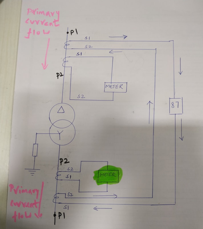
Is the attached arrangement of CTs correct for differential protection of transformer? The "P2" of CTs on both the primary & secondary of transformer are towards the transformer.
xnuke
"Live and act within the limit of your knowledge and keep expanding it to the limit of your life." Ayn Rand, Atlas Shrugged.
Please see FAQ731-376 for tips on how to make the best use of Eng-Tips.
SEL and GE's relays let you set the polarity in the relay. For mechanical, all the currents going into the dot must equal the currents going out of the dot.
------------------------------------------------------------------------------------------
If you can't explain it to a six year old, you don't understand it yourself.
Yes, that look fine.
However, sliding link disconnect terminals are not a great idea on a CT circuit. Most utilities would frown on this due to safety concerns. It would be safer to use regular or shorting terminal blocks.
Q1. Is the attached arrangement of CTs correct for differential protection of transformer?
A1. In most cases it does't matters whether the CT secondaries are earthed on S1 or S4.
However, all [three CTs] must be earthed [consistently] i.e. either all three S1s or S4s.
Most modern protection relay works well either S1 or S4 is earthed, see advice by Mr HamburgerHelper.
Based on the schematic, Power flows from P1 to P2 and all three S1s are connected to
the protection relay and the kWh "in" (+) terminals. The kWh "out" (-) terminals finally
earthed together with all S4s is [in order].
Attention: The kWh meter needs three-phase voltage input (which is not shown in the
schematic) must also be [correctly phased] and the ["in" and "out"] directions observed.
BTW: From the schematic, it does [not] seems to a " differential protection" . It seems
to me that it is a standard "over-current" protection.
However, if your doubt is on whether to earth the common S1s or S4s, then the correct terminology to be used whether it is a " differential protection" or "over-current" is irrelevant.
My question is related to the position of the primary of CTs for differential and REF protections.
Generally P1 of the CT is connected to the source side and P2 is connected to the load side.
In the above image, consider the top portion as primary of the power transformer (source side) and the bottom portion as secondary of the power transformer (load side)
In the top portion, the P1 of the CTs are connected to source side.
In the bottom portion, the P2 of the CTs are connected to the source side.
Though this arrangement causes the CT secondary currents to oppose each other during normal operation so that the operating relay coil making the net current zero.
However if there are other cores in the CT are supplying to Metering & O/C protection, there is a possibility to connect it in reverse polarity. How is it done at site?
Q1. My question is related to the position of the primary of CTs for differential
and protections.
A1. The circuit shown is a standard over-current protection + metering. It is [not]
going to function as a " differential and REF protections". The (protection relay)
shown in your circuit is [not] a [differential protection relay] and the circuit
is [not] wired for [REF protection] either.
Have you submitted a [wrong] circuit?
My apology if I had misunderstood what are you asking.
Yes, it is not connected to the Diff/REF relay in the above picture. That is why I asked you to consider. These pictures are not related to my project.
If these CTs are connected to the Diff/REF relays, is the position/polarity of the CTs are correct. As I studied, these position of CTs are correct for differential relay. However if there are other cores in the CT in the bottom portion are supplying to Metering & O/C protection, there is a possibility to connect it in reverse polarity. How is it done at site?
I assume that "PROTECTION RELAY" is the source side terminals of the differential relay. You don't show how the secondary of the load side CTs are connected to the differential relay, so we cannot say if they are connected correctly.
If understand that "P2" (Primary) of the CTs to be positioned towards the protected object; My question is concerned with the other core in the CT supplying to Metering in the secondary of the power transformer - green highlighted in the below image, Is there a possibility to wrong polarity connection to the metering as the primary current direction in the CTs are from P2 to P1.
Yes, your green meter will likely indicate reverse power flow for the situation shown if you connected it just like the other one. It can be corrected by reversing the current connections or the voltage connections. Many of the new digital meters allow for making the correction in the settings.
If your question is pertaining to the unshaded and shaded green [current meter] which is
[not] a kWh meter, the meters will act [positive reflection ] irrespective of whether power
is flowing from P1 to P2 is reversed or S1 and S2 is revered connected.
Attention: 1. A panel [current meter] irrespective of type is [not] a [directional indication
device]. They always have [positive reflection], [irrespective of the direction of power/current flow].
2. However, a [kWh meter] is sensitive to the phasing and direction of current flow.
3. Also a [reverse-power relay] is sensitive to the phasing relationship between the voltage and current direction of the current flow.
I assumed the green meter was a kWh or power meter with the voltage connection not shown like that shown in the first diagram. Upon review, the first and second diagrams are completely different. If just an ammeter, no direction can be indicated as Che stated.
In many digital relays, ABB for example, how the CT polarities are wired in differential relaying 'does not matter', not in the real sense of the word but you just inform the relay that the CTs are wired Type I or Type II. The relay will then internally compensate the current flow directions based on the CT type connection you input to the relay.