Continue to Site

Eng-Tips is the largest engineering community on the Internet

Intelligent Work Forums for Engineering Professionals

  • Congratulations cowski on being selected by the Eng-Tips community for having the most helpful posts in the forums last week. Way to Go!

Concrete Breakout Strength decrease 1

Status
Not open for further replies.

Italo01

Structural
Sep 4, 2021
169
Hello,

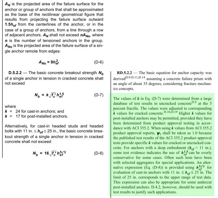
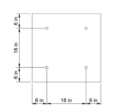
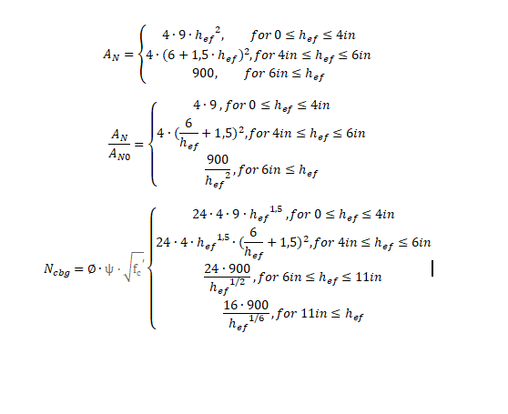
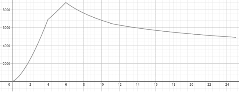
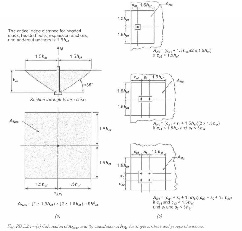
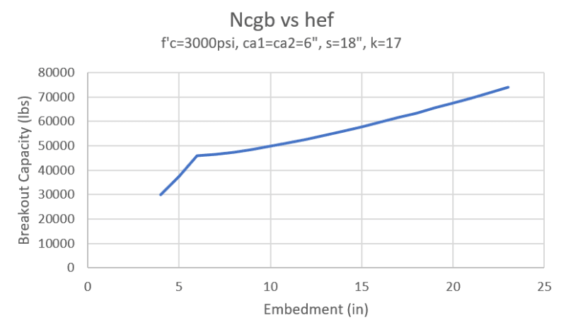
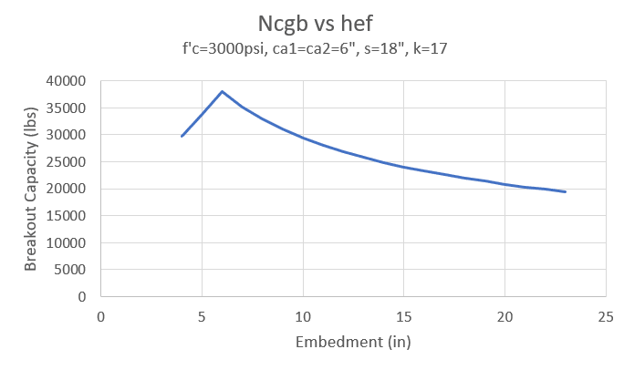
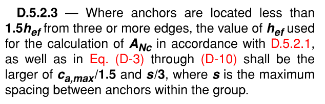
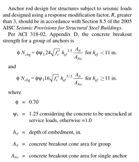
I have a question regarding Conrete Breakout strength. The strength of the anchor group to Breakout varies with exponent 3/2 or 5/3, depending on the anchorage length. If the area of the Cone reaches the edges, i.e., AN is maximum, the strength will decrease with a anchorage length increase. Does Anyone know why this happens?

Anchorage_force_ndbdif.jpg


Thank You.
 
Replies continue below

Recommended for you

Can you run a small example to show how you are concluding that increased length is giving decreased strength.

If you think about the geometry the deeper the anchors go, the more likely there will be overlap in the breakout cones. But it shouldn't be less total strength for the group. I think working through an example with some real geometry you can answer/clarify your question and understanding.
 
Because if your anchor is deeper, you wont get the full area of the cone (reaches the edge). So at some point, increasing the embedment will not be as effective because your cone will not be square and more like a rectangle.
 
All else being equal, the change in strength from 10.99in to 11in is less than 0.6% the wrong way (strength reduced as the embedment gets 0.01in longer). Sounds like the error produced when trying to best-fit a formula to empirical results.
 
See the code's commentary below.

But ACI- 318-02 is old and long superseded, you should use the latest code.


Capture_ncc1th.jpg
 
Hi, thank you all for your inputs.

PhanEng, my question its not about the transition at the discret point hef=11in, but the continuous decrease.

Hetgen, i understand this but even considering the two curves the decrease occurs.

This decrease, considering the case of a square pattern of anchors, occurs when hef is greater than a third of the distance between anchors and 2/3 of the distance between anchor and edge. At this moment, AN remains constant for an increase in hef, AN0(denominator) increases with hef squared, so the total strength effectively decreases.

Lets take this particular case:

bc00106b-86b2-43c7-bf96-5eef1019db5f_xeexes.jpg


For this case, we can obtain:

Equation_ttsofg.png


Neglecting the constants, we obtain the following curve:

Curve_osagvp.png


This means that, according to the model, for an embedment length above 6in, the breakout strenth decreases for an embedment length increase.

For this particular case, the breakout strength for hef=8in is 13% smaller than for 6in and for 10in is 23% smaller, so if this model is accurate, then someone that calculates an embedment length for a situation similar to this, and thinking that is acting conservatively, uses a greather anchor rod is actually greatly reducing the strength.

Did a do some mistake?
 
That's just the effect of the 6" edge distance changing the ratio of An to Ano. You'd expect once your depth is below 9"/1.5 that the entire plinth is mobilised and there is no further increase. Your plot doesn't suggest this?

 
Yes, i understand why there's no increase at this point, but my point is that i expected the strength to remain constant and not to decrease.
 
You're limiting the embedment depth right as per the code when you get more than one edge limiting the breakout surface? Not doing this may lead to the point you're observing? I forget the exact details, but in ACI it's something like if c1 is the min edge distance and C2 is the next closest edge distance then you artificially limit the effective embedment to c2/1.5 or something like that for the calculations to be valid (there is a few other requirements, so look at the ACI code in chapter 17)

 
There are some issues with your equations. Just taking a quick look, for the first case, your An = 4*9*hef^2 and your An0 = 9*hef^2, but you are saying your An/An0 = 4 * 9 when it should equal 4.

I haven't looked too far into your other equations, but they look a little funny too (eg there's a hef^1/6 in there). Make sure you are following this helpful diagram (this is taken from ACI 318-11).
ACI_318-11_Figure_RD.5.2.1_q7rjrc.png


Here's what I came up with from your geometry based on the ACI figure:
Breakout_vs_Embedment_sds8q9.png
 
Realizing that you're talking about the case where all 4 edges are limited such as installing on a pedestal, I do see what you're saying about the capacity decreasing with increased embedment depth. You get to a point where Anc stops increasing and you have Ncbg = Anc/Anc0 x Nb times a bunch of constants and Ncbg ends up being a function of hef^1.5 / hef^2 which obviously decreases as hef increases.

I think the exponents came from some testing data that may have been based on a maximum of two edge conditions and breaks down in the case of four edge conditions. I think I have a paper I can dig up that talks about some of this stuff
Breakout_vs_Embedment_Pedestal_hdhjil.png
 
Chris3eb/Italo01, as I mentioned in my previous reply, when influenced by multiple edges you need to artificially limit the effective depth to the maximum value noted in the code. That addresses the h_ef^1.5 term in so far as it then becomes a constant for the purposes of the calculations, as is everything else in the equation at that point also being a constant as you've mobilised the entire plinth effectively as the breakout surface. So for increasing depth the capacity is then constant as I noted previously.


Agent - yes, you're right. Here's what ACI 318-11 has to say about that:

ACI_318-11_D.5.2.3_zojldx.png
 
Status
Not open for further replies.

Part and Inventory Search

Sponsor