Continue to Site

Eng-Tips is the largest engineering community on the Internet

Intelligent Work Forums for Engineering Professionals

  • Congratulations cowski on being selected by the Eng-Tips community for having the most helpful posts in the forums last week. Way to Go!

Close Column Offset on Transfer Slab 1

Status
Not open for further replies.

efFeb

Structural
Dec 25, 2019
68
Hi,
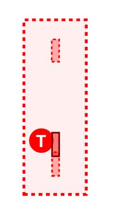
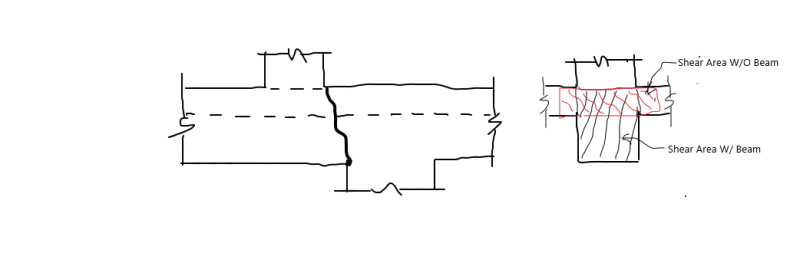
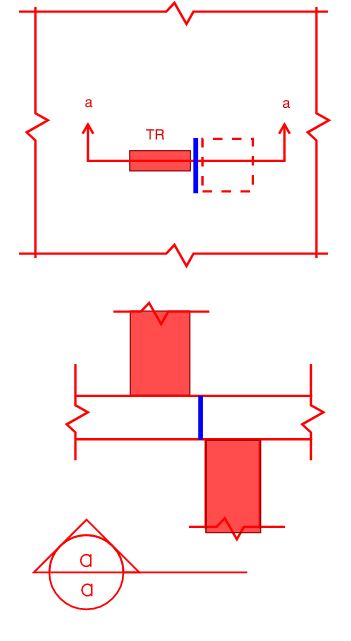
I'm designing a transfer slab that has a number of columns transferring near supports below. What I am most concerned/unsure about is shear along the plane shown in my attached sketch. What I would like to check here is 1. Interface shear between the column below and transferring column above and 2. Local one-way shear between the two columns at the location shown in blue.
I'd love your input, if you've come across similar situations in the past, on these and any other checks that might need to be considered. I'd be especially interested in hearing your thoughts on what width would be reasonable to consider for the local one-way check, and on whether adding horizontal reinforcing for an interface shear condition is necessary if I have satisfied one-way flexural shear at this local region.
close_column_offset_m8lqk1.jpg

Thanks so much for your time!
 
Replies continue below

Recommended for you

I think as opposed to what you've proposed (abruptly changing column offset and reliance on the slab), the typical way to detail this scenario would be to overlap the columns in one or more storeys, creating a larger column capable of dealing with the transition in force.

If the architect doesn't like that, we'll it's one of those situations where they have no choice... Loadpath, Loadpath, Loadpath....
 
I also feel as though this situation may result in some high unbalanced moments in a two way shear check. I agree with Agent that overlapping is preferred. Perhaps a walking column type situation would work architecturally where the total shift is made up over a few floors.
 
Be firm with the architect and outline your position. I’m not a fan of this detail. Overlap as suggested above.
 
If you are trying to do this without an offset, it is not a flexural condition. A strut and tie analysis and design is required. But that would require a lot of depth in the slab.

Take the advice you have been given above. Make one or both of the columns larger.
 
I think most of us agree it is preferable to overlap columns to have a more direct load path.

But that being said how is this situation worse than any other transfer arrangement?

At least with this one the load can strut down quickly rather than transferring many metres. So why is this one to be rejected out of hand?
 
Depending on the geometry, you might use a slanted column so that they align. This is not unheard of. And the architect might give you a hug, or at least see the error of her ways.
 
Tomfh,
The geometry needs to be adjusted from the OP's sketch, either in the slab or in the columns.
 
Check the one way shear at the interface of columns, use a bend band width equal to the upper column width plus one times slab thickness. Since shear reinforcement could be both difficult and ineffective, the only way is as pointed out by hokie66 - add slab thickness. Also check two way punching shear with perimeter length consists of 3 sides only.
 
Maybe add a beam below, if permitted?
 
Hokie66,

I agree it’s not a nice arrangement, but if the slab has adequate shear capacity at this junction then why does it need to change?
 
Don't get me wrong. I don't like it either. In fact I hate transfers more than anyone. But provided there's enough concrete in the slab junction to carry the shear forces I don't see why it can't be made to work.

 
Thanks everyone for the feedback so far;
I'm just curious, there have been some suggestions to add a beam. I'm having difficulty understanding how adding a beam really changes the situation. I think that i would still be worried about the same condition. For example, if I had a condition like im showing in the attached sketch, I have a feeling that people would see this as being less concerned, but I am not quite sure why. I would still be concerned about the same condition here. If you could help me to understand, that would be great; I am just doing the detailed design on this job and don't want to flag issues if the issue is just me overthinking.
Thanks so much,
bm_transfer_lann20.jpg
 
In order to understand it, you need to develop a truss analogy, usually referred to as strut and tie method. If you don't know how to do this, there are tutorials available.
 
A beam below is a increase in concrete depth to resist shear, instead of increase depth of the slab globally. Yes, the same problem still exist, but you have a stronger section. Not ideal, but should work.

s_c5lb8s.png
 
How thick is the slab and what is the transfer load?
 
Agree with hokie66 in this instance throw what you know about beam theory and one-way shear out the window and look at a strut-tie response.

If you don't want to do a detailed strut and tie analysis, as others have said, go to bat for an increased column size to act as a transition element between the two column locations, how you coordinate this situation now will impact how you deal with similar conditions in the future with this architect.

My Personal Open Source Structural Applications:

Open Source Structural GitHub Group:
 
How do you develope the column rebars with so large an offset?
Assuming a 10" x 36" column load at a modest 3 ksi is over 1000 kips with a minimum moment of 0.1 x thickness and would not transfer forces to the column below. It would need a superthick slab or beam system and an architect who provides a high ceiling height.
 
Status
Not open for further replies.

Part and Inventory Search

Sponsor