Continue to Site

Eng-Tips is the largest engineering community on the Internet

Intelligent Work Forums for Engineering Professionals

  • Congratulations cowski on being selected by the Eng-Tips community for having the most helpful posts in the forums last week. Way to Go!

Cable bundle

Status
Not open for further replies.

ChangeOrder

Structural
Mar 26, 2022
13
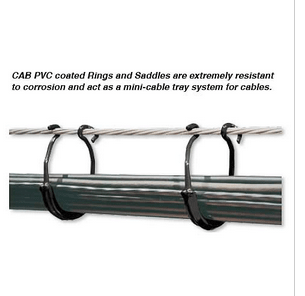
I have a cable bundle on a solar farm running thru a CAB support system. I have seen the quarion of 1.2*sqrt(D^2*number of cables in bundle). Can anyone tell me where this equation came from? Also, would it be realistic to use this to determine the diameter of a cable bundle if it is not a tightly packed cable bundle. Ulimately, i am trying to determine ice load on the cable bundle. Thanks!
 
Replies continue below

Recommended for you

The area of each cable is pi*d^2/4. The total area of n cables would be A = n*pi*d^2/4. If the was no space in between individual cables, like they were all melted into a solid circle, then the diameter of the bundle would be found by solving for the diameter D in the equation A = pi*D^2/4, or D = sqrt(4*A/pi). Substitute for A to get D = sqrt(4*n*pi*d^2/4/pi) = sqrt(n*d^2). The 1.2 allows for the fact the individual cables are not melted into a solid circle but have spaces between cables. If there were 7 equal diameter cables, 6 would fit perfectly around one, like 7 strand conductor. The diameter calculated by the equation would be 1.2*d*sqrt(7) = 3.2*d. Actually, the diameter would be 3*d because there would be 3 cables in a row.
 
In NEC art 392.22 this factor [1.2] is used in order to appreciate the big cables contribution to the total cable tray width.
In my opinion, in a rectangular cross-section area as of a cable tray ,1.3 filling factor it is more close to reality.
However, in a circular area 1.6 it is possible.
Let's say we have 7 cables of 4/0 single core of 0.532" as per NEC Tables and 33 cables of 4 awg diameter of 0.164".
First group of 7 cables of 4/0 will present an outer diameter of 3*0.532= 1.596" in the center.
A layer of 4 awg cable will present 1.596+0.164=1.76" [middle] then a cicumference of pi*1.76=5.5292" and divided by 0.164=33 cables.
The total diameter of the bundle is 1.76+0.164=1.94”
The bundle cross-section area is then 1.94^2/4*pi=2.956 in^2
The total cross-section area of all cables it is: 7*0.532^2/4*pi+33*0.164^2/4*pi=2.2531 in^2.
k=2.956/2.2531=1.312
If the number of 4 awg cables will be 45, for instance, k=1.589
 
If the cables are not tightly bundled, the bundle will not be circular. Calculating ice load would depend more on the perimeter of the bundle. Calculating ice load as a thickness over a circle would be inaccurate. I suggest drawing a bundle in the most likely configuration and measure the perimeter on the drawing, multiply the perimeter by the ice thickness to get the ice area. Even that would neglect the weight of ice forming from water that filled the space between cables.

If you want an easier to calculate, but very conservative approach, calculate the ice loading for each cable independently and multiply by the number of cables.
 
Not sure what you mean by a CAB support system.
Is this it?
Screenshot_2023-06-07_at_14-52-56_PVC_Coated_Aerial_Cable_Rings_from_CAB_-_Cableorganizer.com_dwzwyu.png

Ice load:
jghrist said:
I suggest drawing a bundle in the most likely configuration and measure the perimeter on the drawing, multiply the perimeter by the ice thickness to get the ice area.
Or
Calculate the total area of the combined ice and cables.
Then calculate the weight and area of the cables and apply to the first solution.

Wind load:
Use the overall diameter.

Derating:
For more than three current carrying conductors in a bundle, use an appropriate derating factor.

--------------------
Ohm's law
Not just a good idea;
It's the LAW!
 
Status
Not open for further replies.

Part and Inventory Search

Sponsor