Continue to Site

Eng-Tips is the largest engineering community on the Internet

Intelligent Work Forums for Engineering Professionals

  • Congratulations cowski on being selected by the Eng-Tips community for having the most helpful posts in the forums last week. Way to Go!

Beam Deflection (Bending) Force Created?

Status
Not open for further replies.

Mandrill22

Mechanical
Jul 30, 2010
113
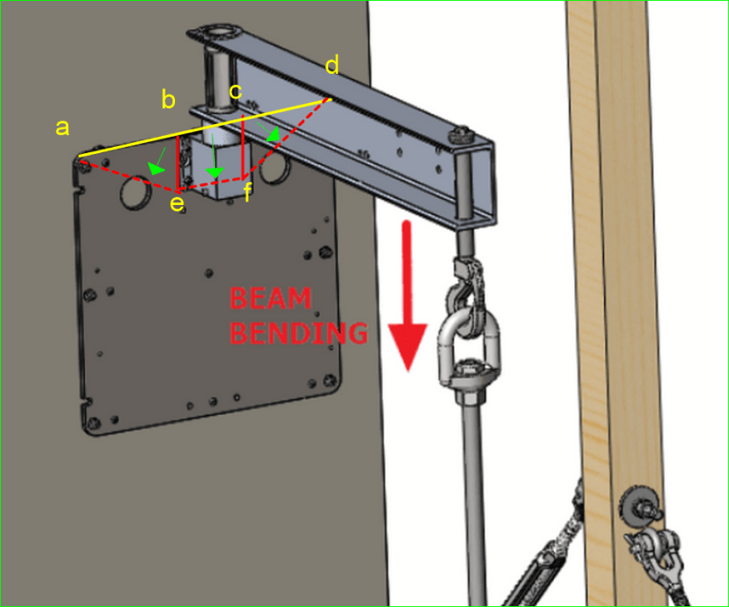
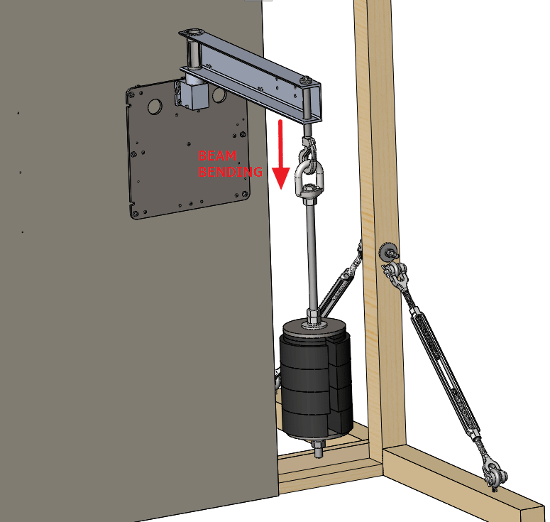
I have a beam bolted to the wall. If I load it on the end, and it bends down 2.5mm (815mm long) at the end, I would think that a force is created on the mounting bolts in reaction to the bending. Is that not accurate? If it is, how would I quantify it?
BEAM_gwhwpx.png
 
Replies continue below

Recommended for you

The bolt will have shear force in it, V = F/number of bolts, and tension caused by the bending moment (M = F*lever arm). The compressive force will be resisted by the connection plate.
 
If the beam is loaded to its capacity, the plate appears to be much too thin.
If the plate remains rigid, the bolt forces can be calculated. Otherwise, they cannot.
The top bolts each carry tension T. The middle bolts each carry tension T/2. The bottom bolts carry zero. All six bolts carry a shear of F/6 where F is the load on the cantilever.
Let vertical spacing of bolts be sp.
Then 2T*2sp + 2*T/2*sp = M where M = 815*F.
i.e. 5T*sp = M; so T = M/5sp = 163*F/sp

If the plate does not remain rigid, all bets are off.


BA
 
the four fasteners carry the applied load (in shear, P/4) … a reasonable assumption but you'll get endless comments about the load reacted by friction and the reality that the four bolts won't evenly react the load due to clearances with the holes. (In reality, the shear is carried by friction but we don't use this loadpath in analysis.)
and the offset moment (M = Pl, yes? … "l" is the distance from the supporting plate to the load)
The moment is reacted by a couple, tension in the upper (2) bolts and compression on the bottom edge.
tension = M/2h … "h" is the distance from the bottom edge to the upper bolts CL. (This is conservative; BA used the other fasteners, but their contribution is small.)

Note, much of your tip deflection is probably coming from rotation of the supporting housing and shaft (and possibly rotation of the supporting plate)


another day in paradise, or is paradise one day closer ?
 
A more difficult question is "how to determine the minimum thickness of the anchor plate".

BA
 
If you assume rigid, then use the compressive force times the edge to edge of the bolt in compression. Or use concept similar to reinforced concrete design, assume a rectangular compressive stress block. Yet, use linear distribution, assume a triangular stress block. Enjoy it :)
 
oh, you guys are looking at the plate … I was looking at the fttg.

the biggest issue is out-of-plane bending along the top edge … easily fixed with a stiffener (angle).

another day in paradise, or is paradise one day closer ?
 
rb has a good point, maybe check the bending just below the pin socket, assuming flexible plate.
 
BeamDeflection_1_ngnebf.png


These look to me like critical yield lines. The yellow line is the edge of plate, so not a yield line. Dashed red lines are valley like. Solid red lines are ridge like.

The green arrows represent fall lines if the plate was flat on the floor instead of on the wall. Rectangle bcef rotates about ef and the two triangles rotate about ae and df respectively. A large hole on ae and fd makes those yield lines even more vulnerable than they otherwise would be.

If the plate is not strong enough to resist those yield lines, the plate is not a rigid body and the earlier calculation of bolt tension is completely wrong.

BA
 
Pay attention to the back of the pin holder, it looks like another hole behind it, I start to think this is an electrical plate (see the rigged edge and small nail/screw holes), and the lifting device is connected to something behind the wall.
 
Status
Not open for further replies.

Part and Inventory Search

Sponsor