Pupsocket
Mechanical
- Jun 23, 2023
- 4
... or is "surface profiles" the better plural?
Hi group,
I'm Karl, new here, long time tech/mechanical designer, very limited GD&T experience. I have a concept that must be fabricated, and while I can describe it to a machine shop with plenty of words and hand waving (the way it was described to me), I'd rather specify it in such a way that they don't tack on a $1000 design line item on their quote just for an hour's work interpreting my hand waving.
My issue involves proprietary items and designs, but I've simplified the CAD model. Here goes:
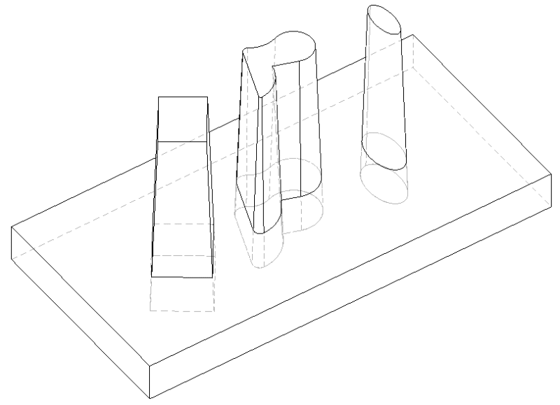
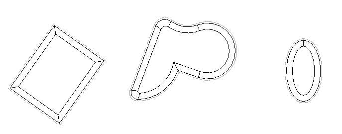
The concept consists of three tapering parts of complex cross section that taper consistently smaller as they go up. These three parts are held in alignment by being pressed lightly (transitional fit) into a base containing complementary holes. Parts will be either tool steel or some type of stainless, most likely made with wire EDM. The example shown has a 3/4" base, 3" of exposed tapers, and the tip profiles are offset in .1" from their form at the top of the base.
Criticals:
Form of each taper's sides (functional requirement, ±.0005)
Spacing of tapers and holes relative to themselves (functional requirement, ±.001)
Form of each hole (assembly requirement±.0025 ±.00025 relative to tapers)
Non-critical:
Overall size of base
Question:
I've used relatively uncomplicated GD&T callouts on relatively simple part drawings. This one is beyond my experience, and searching online I couldn't find helpful examples. I am thinking profile of surface for each taper, but I'm at a loss for the base holes. Specifying two side datums and controlling the holes seems unnecessary if there's a way of specifying a datum based collectively on multiple surface profile features.
What would be a good strategy to capturing the above intents? Let me know if anything important is ambiguous; I'm trying to balance details while not exposing IP.
Thanks in advance!
Karl
Hi group,
I'm Karl, new here, long time tech/mechanical designer, very limited GD&T experience. I have a concept that must be fabricated, and while I can describe it to a machine shop with plenty of words and hand waving (the way it was described to me), I'd rather specify it in such a way that they don't tack on a $1000 design line item on their quote just for an hour's work interpreting my hand waving.
My issue involves proprietary items and designs, but I've simplified the CAD model. Here goes:
The concept consists of three tapering parts of complex cross section that taper consistently smaller as they go up. These three parts are held in alignment by being pressed lightly (transitional fit) into a base containing complementary holes. Parts will be either tool steel or some type of stainless, most likely made with wire EDM. The example shown has a 3/4" base, 3" of exposed tapers, and the tip profiles are offset in .1" from their form at the top of the base.
Criticals:
Form of each taper's sides (functional requirement, ±.0005)
Spacing of tapers and holes relative to themselves (functional requirement, ±.001)
Form of each hole (assembly requirement
Non-critical:
Overall size of base
Question:
I've used relatively uncomplicated GD&T callouts on relatively simple part drawings. This one is beyond my experience, and searching online I couldn't find helpful examples. I am thinking profile of surface for each taper, but I'm at a loss for the base holes. Specifying two side datums and controlling the holes seems unnecessary if there's a way of specifying a datum based collectively on multiple surface profile features.
What would be a good strategy to capturing the above intents? Let me know if anything important is ambiguous; I'm trying to balance details while not exposing IP.
Thanks in advance!
Karl