Continue to Site

Eng-Tips is the largest engineering community on the Internet

Intelligent Work Forums for Engineering Professionals

  • Congratulations cowski on being selected by the Eng-Tips community for having the most helpful posts in the forums last week. Way to Go!

True Profile Definition

Status
Not open for further replies.

pmarc

Mechanical
Sep 2, 2008
3,227
Hello,

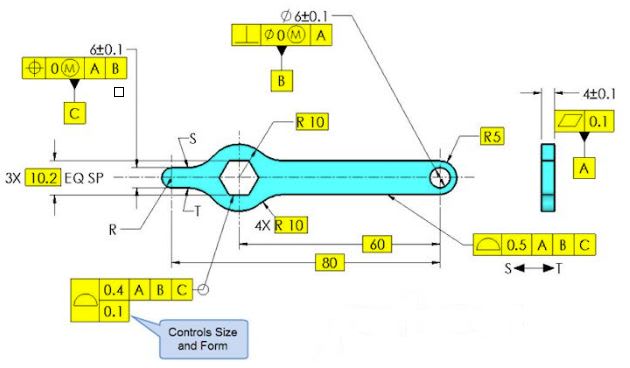
Below is a snapshot taken from the most recent Tec-Ease tip available on their website. My question would be following: Does anyone think that the true profile between points S and T (clockwise) has not been fully defined? I am specifically thinking about close vicinity of points S and T. Thank you!
capture_bjnd61.jpg
 
Replies continue below

Recommended for you

Yes, location of points S and T seems questionable. Unfortunately, should this be real world application, no-one would care (including customer).
Given that profile tolerance is far greater than position, the possible error will be ignored.
With some extension of principle transition zones per Para 8.3.2.2 could be recommended.
But I am also curious about other possible interpretations. :)


"For every expert there is an equal and opposite expert"
Arthur C. Clarke Profiles of the future

 
Just to start the conversation, knowing pmarc and due to the fact he hasn't started a new thread in years, I am sure he is up to something.
I found these attachments (part 1 and part 2) in my collections.

Why not the same question is to be valid to the cases attached?
If pmarc's question is not valid ("Does anyone think that the true profile has not been fully defined?") is that because in his case datum feature C is part of the profile callout?


 https://files.engineering.com/getfile.aspx?folder=dfc92954-e048-41ff-bb69-d93077c3c1fd&file=Hole_and_Slot_-part_1.pdf
pmarc,

I would say that the true profile is not fully defined, because the C width is a directly toleranced dimension and not basic. Is that what you're getting at?

greenimi,

I'm not sure about the other cases with the round-end slot, I'll have to think it through. This would be a different issue, however.

Evan Janeshewski

Axymetrix Quality Engineering Inc.
 
greenimi,
You sometimes see too much in my comments;-) I was merely interested in knowing if anyone else sees any problem with how they dimensioned the true profile.

Evan got my intentions correctly. Because the width C is not basic the distance between arcs starting in points S and T is not basic, and therefore the true profile between points S and T is not fully defined.

Before I posted the question here I sent this comment to Tec-Ease along with some other remarks about other mistakes they made in the original version of the tip. It was about a month or two ago. They incorporated the other remarks but not the one about true profile. That is why I thought I would ask the question here just as a sanity check.

Looks like I am not the only one that sees problem with this definition.
 
greenimi,
Neither of the two definitions have the same issue.
 
pmarc,
When you get a minute, could you, please, give some more details (theory-wise, as realty-wise is already covered by CH as "not applicable" or not a concern) on why you see an issue on your scheme and not on the other two I have posted (again from the same source)?
Thank you pmarc for your help
 
@greenimi:
I didn't say it was "not a concern" or "not applicable". The drawing could confuse anyone else, just like it did to pmarc or myself.
I am just saying the issue could be overlooked, intentionally or not.
Imagine programming CNC to cut the outline of the part. If the machine could produce tighter tolerance on "west" side of the part, there is no reason to worry about two-and-a half times larger tolerance on "east" side - it will be OK.
It may be that larger profile tolerance represents "as cast" section of the part while smaller position tolerance is for machining. Then some distinction would be made on the drawing.
All I was trying to say, that something (or nothing) would be done for part to be accepted.

"For every expert there is an equal and opposite expert"
Arthur C. Clarke Profiles of the future


pmarc,
The video I found on youtube has profile all around. Probably this is the version/ revision zero. --see also my attachment--
Correct me if I am wrong, but I guess someone complained that datum feature C is self-referencing in the FCF of the all around profile (maybe you??) and they have changed it to profile between points (S and T) and they created the issue you are discussing in this thread. Tec-ease created version/revision one shown by you. Get rid of one problem and created another one.

Why use tertiary datum C in the first place anyway? Why not reference everything to A and B only and no more problems?
We already know that tertiary datum feature has multiple problems.


greenimi,

"My" example:
The problem is that the vertical distance between both arcs (or their centers) starting in points S and T is not basic, but depends on the directly toleranced dimension 6 +/-0.1 for width C.

Or looking at this differently, a following question can be asked: if only basic dimensions that apply to the considered contour are left on the drawing, will this set of basic dimensions fully define the true profile in terms of its size, form, orientation and location to the spefied datums? The answer is no, it will not.

"Your" example #1:
The true profile of the groove controlled with profile of 0.16 is fully defined in terms of its size, form, orientation and location to the specified datums. The only aspect of the contour/tolerance zone geometry that is not fully controlled with basic dimension(s) is the length of the arcs consituting the tolerance zone boundaries. That length depends on the actual diameter of the datum feature A, but that is not a problem as geometric tolerance zones always extend to the full length of the toleranced feature.

"Your" example #2:
The same story. The true profile of the face controlled with profile of 0.3 is fully defined in terms of its form, orientation and location to the specified datums (no size involved here). The only aspect of the contour/tolerance zone geometry that is not fully controlled with basic dimension is the length of the planes consituting the tolerance zone boundary. That length depends on the actual diameter of the dia. 32 cylinder, but again that is not a problem as the length of the planes must be equal to the actual length of the toleranced surface.

So to summarize, in all 3 examples the length of the profile tolerance zones at the ends is not fixed (which is not a problem), but only in "my" example the true profile size/form is not fully defined "inside" due to one missing basic linear relationship between two arcs.

-----

As for the youtube version of the tip, yes, it shows revision zero that I mentioned. The all around profile was one of the mistakes they made (because only part of the outer contour was defined with basic dimensions). The other thing they corrected/got rid of was flatness tolerance applied to datum feature A. The 0.2 value in conjunction with the width tolerance (+/-0.1) did not make sense.
 
Pmarc,
Thank you very much for your detailed explanation. So, looks like the reason Tec-Ease updated this tip was because the lack of the correct definition of the true profile and not because of the datum feature C being self-referenced in the FCF as I initially thought. I am still learning…..This ever stops.

Just to make sure I understood your solution correctly: are you proposing to add a basic dimension between the centers of those two arcs? (because adding a basic dimension between S and T points might create a conflict with the ± direct tolerance feature….thinking out loud)

Also, why there is no 2X for R10 basic (R10 basic closer to the datum feature B symbol)?

And one additional question about “My” example #1 (January 2012 tip from Tec-Ease): would you say that if 48 basic dimension is replaced by an equivalent basic dimension between the centers of the two grooves then the intent will be the same, no change in the form, size, orientation and location of the groove tolerance zones and the true profile are still fully defined? Am I correct?

Thanks again pmarc
Good learning exercise for me.
 
pmarc,

My interpretation of that drawing is that T and S are at the points where the straight edges connect to the radii. It would be nice if there was some construction geometry that made that clear. The design intent appears to be that the outline to the right of S and T is much less critical than all the other dimensions on that thing.

Does it really matter that the C width is not basic? The C width is a datum, and the radii are specified to be within 0.25 of perfect form. I can inspect for that. That does affect the length from datum feature[ ]B to the beginning of the straight datum feature[ ]C, possibly quite a bit. Maybe this is acceptable. An explicit minimum length to[ ]S and[ ]T would be a good idea.

I do observe that the radius at the left hand end is not controlled by anything. They need to attach a profile to it, or convert the 80mm basic dimension to [±].

--
JHG
 
drawoh said:
I do observe that the radius at the left hand end is not controlled by anything
Since they converted the all around profile to in between points, I would say that the radius at the left hand end is controlled similar to figure 1-29/2009 except it is only one radius (not two as it is shown in the standard. 1.8.4 states: "For fully rounded ends, the radii are indicated but not dimensioned."
That would be my opinion.

 
drawoh,

The problem is that a fixture cannot be made ahead of time to verify the location of the radii. If I want to make an optical comparator overlay, I could do it for all the rest of the outline from S to T except the two fillets at S and T. Instead it would depend on the width.

I think they want to have the benefit of a feature of size as a datum and depend on the magic of machining to make the transition come out OK. I don't know what benefit that would be; they could have made a separate profile tolerance for the left end.

greenimi,

what about the location of the radius? Currently it is located by a basic dimension.
 
Sigh, I missed that 80 basic dimension. Sorry.
Looks like theere are "problems" with this print even if it's made by a reputable training company. Does not look pretty when ± is combined with GD&T.
I have to agree with drawoh that maybe another profile between points at the left end should be added.....

 
greenimi,
Yes, the solution is to add basic dimension between centers of the arcs.

One of the solutions to fix the entire drawing (by fix I mean to make it undisputable but not necessarily dimensioned functionally) could be to define the entire outline of the part with basic dimensions, then apply profile all-around relative to datums A and B to it, and then make basic 6 mm width datum feature C. That would solve the problem of undefined true contour and eliminate the issue of uncontrolled length of the part at the left end.

Regardless, I am kind of surprised that they did not correct the drawing in the video.
 
Looks like is not easy way to combine ± dimensions with GD&T (and not be subject to multiple interpretations or unambiguous). That’s probably because ± dimensions are “by definition” ambiguous.

And to clarify the “video” issue you brought up: my previous link is from an youtube video (the older/initial video version). They did update and correct the drawing in the video they have on their own website! –link below--


I guess the youtube version will have to wait longer to get (if ever updated) the new and somewhat improved drawing version.

Still confused, why do you need/insist for datum feature C?
 
Status
Not open for further replies.

Part and Inventory Search

Sponsor