Continue to Site

Eng-Tips is the largest engineering community on the Internet

Intelligent Work Forums for Engineering Professionals

  • Congratulations cowski on being selected by the Eng-Tips community for having the most helpful posts in the forums last week. Way to Go!

Tables for Sloped Retaining Walls 1

Status
Not open for further replies.
Replies continue below

Recommended for you

Bootlegend:
I doubt that you are going to find something like that in some tabulated form or some simple formula format. Why not just assume 3’ @ 18’ on the left edge, then design for 4 – 10’ wide units with their max. heights as the design height for the next 10’. These should be able to be picked out of std. tabulations for the given design heights. Maybe only use 8’ or 5’ width increments from the tables. This width incrementation should be for rebar cages which you can made up on saw horses, on the ground, and then lift (tipped up) into the vert. position, and tied together. Almost anything other than that, constantly varying rebar spacing for example, would be more confusing, in the bar placement, than it is worth.
 
I was hoping the vertical fixed edge would reduce some of the vertical bending moment at the tall side. There is a rail surcharge very close to the wall.

dhengr said:
Why not just assume 3’ @ 18’ on the left edge
Are you suggesting design this section as a plate fixed on two edges or as a cantilever?


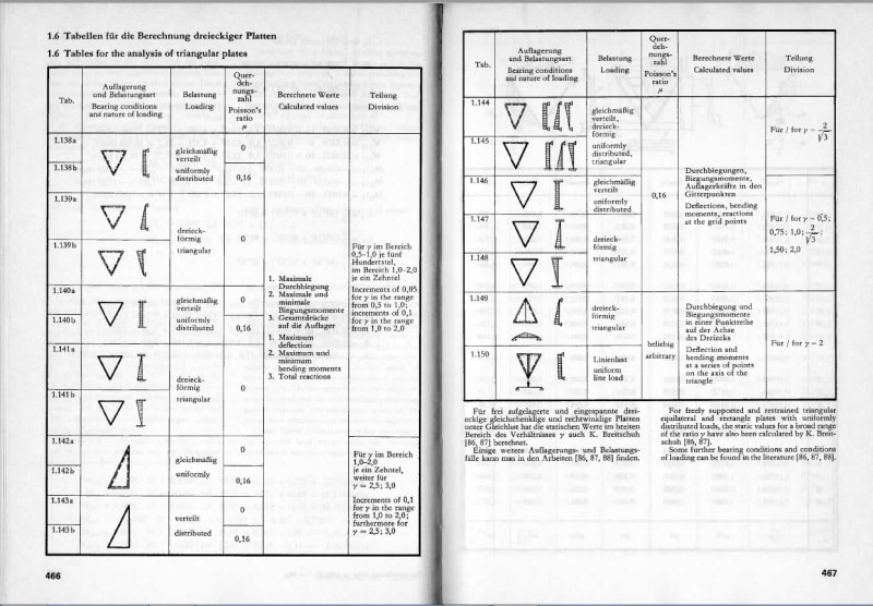
Thanks. That is the Moody document I was referring to. It does not consider triangular plates.

 
For structural design of sloped retaining walls, we typically make what we consider to be a conservative estimate of distribution length along the wall of 5 times the wall thickness and design for the average loading over that length.

For stability checks, we use the loading at the 1/3 point along the length from the high end, assuming it's 'all or nothing' for sliding and overturning. If I'm understanding your post correctly, your surcharge loading has a greater intensity at the high end, so it might be unconservative to even use the loading at the 1/3 point in your case.

If the wall is restrained at the ends along the height or at the top, you'd have to consider two-way bending of the wall. If the wall is reinforced concrete, I don't think you could confidently use a formula for a homogeneous plate, even if you find one. You have a few options that I can think of:

1) Ignore the end restraints and design the wall as a vertical cantilever.

2) Make a conservative assumption about how much of the wall is supported by the end restraint on the tall side, and design using the loading at the wall section at the end of the assumed supported section. You'll need to analyze the wall for horizontal bending as well as vertical, but you can do it separately.

3) Create an FEM of the wall, in all of it's gory detail and get the forces and stresses from that.

Unless you have a large number of similar walls, Option 3 would likely be more of an expense than it's worth. It reminds me of a sign one of my coworkers had in his cube - "Real men do biaxial analysis". I'm apparently not a real man, 'cause I haven't attempted it yet.
 
I know this one :
Bares_00_ltin5r.jpg

Bares_01_xihqv5.jpg
Bares_02_qbs0k1.jpg
 
To reduce the design loading, you could also take a closer look at the variation of surcharge loading at various depths. The uniform equivalent soil surcharge pressures are simplified approximations of the actual pressure distribution curves. The AASHTO bridge spec. has formulas for calculating the surcharge pressure for various loading types (Section 3.11.6).
 
HotRod10 said:
1) Ignore the end restraints and design the wall as a vertical cantilever.
Thanks for the suggestions. I'm probably leaning that direction. I was able to shave a couple feet off the required height so that helped.

HotRod10 said:
take a closer look at the variation of surcharge loading at various depths.
I have used the Boussinesq equations for a strip loads you mentioned. That leads to another question. If designing the sloped walls as cantilever would you use at-rest or active pressures? At what angle of the intersection with the main structure (see attachment) is the wall considered braced? In order to move on I think I'll just use at-rest for the entire length since the retained height is reduced along the length.

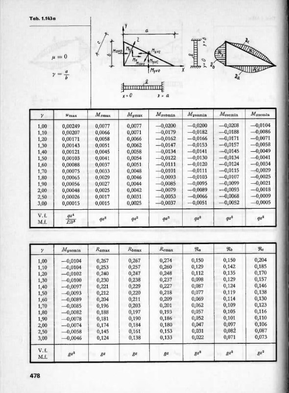
Thanks! Those are nice tables and they do look like they would apply to my situation. I tried to track a copy down but it looks like that's a hard book to come by.
[URL unfurl="true"]https://res.cloudinary.com/engineering-com/image/upload/v1566929522/tips/plan_ygi5ci.pdf[/url]
 
As a minimum, I would suggest using the at-rest pressure when designing the restrained portion of the wall. At-rest is the pressure a wall theoretically is subjected to if cannot move, so that the soil is not able to mobilize the internal friction (particle interlock). It takes a certain amount of movement before the particles within the soil develop internal resistance. The amount of movement varies by soil type. Because yours is restrained at the high end, I would take the safe and simple route of designing for at-rest pressure everywhere. The reduction using active pressure for the shorter portions of the wall isn't likely to change the configuration or the reinforcing substantially when it comes to detailing, anyway. A wall of that length that will be practical to build would typically only have maybe one or two changes in footing width and no changes in stem wall thickness.
 
Status
Not open for further replies.

Part and Inventory Search

Sponsor