Continue to Site

Eng-Tips is the largest engineering community on the Internet

Intelligent Work Forums for Engineering Professionals

  • Congratulations cowski on being selected by the Eng-Tips community for having the most helpful posts in the forums last week. Way to Go!

supporting a #6314 bearing

Status
Not open for further replies.

RoarkS

Mechanical
Jul 10, 2009
264
Okay bearing gods...
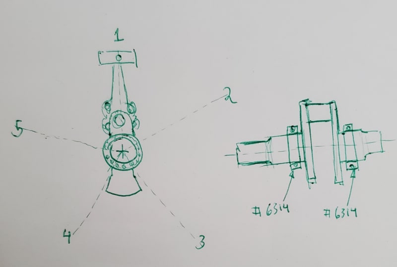
I'm trying to develop the case for ICE engine to support the main bearings #6314

I've gathered that both the race and inner ring needs to be an interference fit.
I'm machining the housing out of Aluminum 6061-T6.
The shaft is probably 4130 RHC 30-35
operating temp is 185-210°F 245 redline.

I'm thinking I need a steel top hat the bearing is installed in, then a slip fit into the aluminum housing and secure it using a few screws.

Ideas? this is much bigger than stuff I typically play with. A little out of my comfort zone.
 
Replies continue below

Recommended for you

It is not clear what are proposing. Why do you think both races need an interference fit? That is almost never done with a bearing of this type. A drawing is needed to provide clarity.

Johnny Pellin
 
20191220_084017_1_mgltvs.jpg

Diagram attached.
5 Cylinder radial. 4 stroke. firing order 13524

I initially thought I would need to have it press fit into the housing (or steel top hat), and let the crank be a slip fit. That would make assembly much better. However I had a few people recommend both be interference because of the load... honestly part of why I'm here.
 
Old business - RE: inner and outer race fit.


===========.

Now the steel top hat primary OD will be subjected to several thousandths clearance when the aluminum case gets warm/hot.
What are "a few screws" going to think of being subjected to impulses of several hundred pounds of force in varying directions 1000s of times every minute?
There will also likely be a tendency for the varying load to make the steel sleeve creep like a friction drive with ratio of Housing ID/insert OD.

Note this is NOT slipping or spinning. Quite the contrary. The greater the radial loading, the greater the tendency for the steel hat to just roll along, but with unavoidable micro-slipping due to variations in surface geometry.

The end results are Perfect conditions for Fatigue, fretting, and other destructive phenomenon, just as if the bearing were fitted directly to the aluminum housing, although perhaps with slightly greater operating clearance.
 
Okay...
So I figured out that one of the engines I've been looking at pretty hard for inspiration uses separable roller bearings.
I spent a little while looking at whats out there and nothing I could find was had enough RPM.

RPM 2700 is MAX... I could limit 2700 to say takeoff/climb so perhaps 2500 RPM is continuous.
Oil SAE 50
Max temp 245°F. 185 - 210°F is normal range.
13,610 lbs is my radial load. Edit: that's an over estimate based on direct gas pressures... which I've found to be pretty close to the true design inertial force along with the typical safety factors (which I haven't determined inertial yet because the masses are not finalized yet)

Typically there is a thrust bearing separate from the two main bearings that handle the propeller load. I've been calling it 1000lbs. Probably more like 300-500lbs.

The question is... What about using a pair taper roller bearings? I've been looking at #32314.

Thoughts?

 
Status
Not open for further replies.

Part and Inventory Search

Sponsor