Continue to Site

Eng-Tips is the largest engineering community on the Internet

Intelligent Work Forums for Engineering Professionals

  • Congratulations cowski on being selected by the Eng-Tips community for having the most helpful posts in the forums last week. Way to Go!

Slot in plate - best end shape for minimum stress?

Status
Not open for further replies.

dculp1

Mechanical
May 16, 2006
75
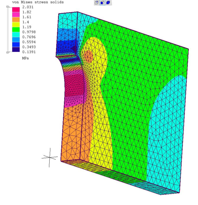
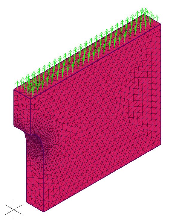
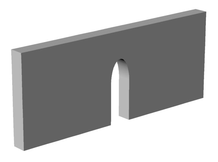
The image shows a plate with a 10mm wide slot. In this design the slot's end shape is a 20mm x 10mm ellipse. A uniform tensile load is applied to the plate's top surface (the narrow surface at the top of the image). Compared to a slot with an R5mm end shape, the von Mises stress is 23% lower.

Besides an ellipse (and possibly a polynomial), what other end shapes should I consider in order to minimize the stress? (I seem to recall a shape that approximated the surface streamline of a fluid flowing through an orifice but I haven't been able to find this again.)

Thanks,
Don C.

Slot_with_elliptical_end_1a_d2riw5.jpg
 
Replies continue below

Recommended for you

you want the largest possible radius at the end ... the major axis of an ellipse.
The largest radius is a flat ... but this creates two 90deg corners. The largest radius then is 1/2 a slot width.

an oversized circle works well ... for a 10mm wide slot, use an hole radius 10mm (or more).

If this is a school project then
1) it shouldn't be here, and
2) the best solution is to dump the slot altogether, and cut the bottom edge diagonally.

another day in paradise, or is paradise one day closer ?
 
The highest stress occurs just in front of where the ellipse transitions to the slot walls, not at the tip of the ellipse (see the top FEA image). Therefore, a gentle curvature is needed in this transition region.

The slot is required for proper operation of the device.

Using an oversized circle isn't possible because of other design considerations. (Although this is currently a preliminary static analysis, ultimately the plate will vibrate parallel to the slot axis.) I am considering a R5mm circle with reduced slot width (a keyhole slot) which will be similar to what you suggest. I will have to run the FEA to see if there is any improvement.

For clarity, the bottom FEA image shows the face load.

No, this isn't a school project (not sure why you thought so).

Slot_with_elliptical_end__von_Mises_stresses_1a_tu7vys.jpg


Slot_with_elliptical_end__static_load_1a_syvbzx.jpg
 
If your software allows for that, run shape optimization to find the best shape for that slot.
 
Unfortunately my FEA doesn't have any optimization capabilities.

I am hoping that someone can suggest an analytic function (e.g., gaussian or similar) that is already known to be better than an ellipse in this situation. I couldn't find anything online or in my textbooks but I'm pretty sure that such exists.
 
why a school project ? ... 'cause I can't see this being a real engineering question. The difference from a full round end to any other profile is likely to be so small as to be negligible.

I hope you are running non-linear ... as the tip of the slot is bound to be yielding under any sort of real load.
Hope you're using TET10s.

Oh, now I see your loading .. I assumed it was along the part, across the slot.
What if you made the plate in two pieces (and got rid of the slot) ?

How uniform is the load ? truly uniform in practice ??

If you really want to reduce the stress, produce the slot from a hole, ie drill a hole first. Then coldwork the hole, then cut the slot.
An alternative is to "coin" the material around the slot.


another day in paradise, or is paradise one day closer ?
 
The slot is required for proper operation; this requirement can't be changed.

Some parts will be made of aluminum and some of titanium. For this preliminary FEA the plate thickness is 13mm. Some actual designs will have this thickness but others may have thicknesses exceeding 300mm. Coldworking may be possible for the aluminum parts but limited for titanium parts.

Assuming that coldworking were possible, I would think that a substantial amount of the initial coldworked compressive stress would be relieved when the slot was later cut.
 
dculp1, I hope you are considering available manufacturing methods as you optimize the slot profile.

Regards,

Mike

The problem with sloppy work is that the supply FAR EXCEEDS the demand
 
Yes, I'm considering how to manufacture but that will be the subject for another post. For the time being I just want to see if the ellipse termination can be improved.
 
yes, cutting the slot would remove much of the cold working stress field, but I think there'd still be some benefit. So I mentioned coining which would probably be better.

I think you've got a bigger variation in your analysis, bigger than the profile of the slot. I doubt the loading would be uniform. I think local (incidental) yielding will have a much more significant impact (than the profile of the slot).

If this is a satellite or military project (where money is no object and minimum weight is Everything) then buy the CAE that will give you the optimum shape for your loads. And optimise the plate ... constant thickness is easy design but not efficient (and a much bigger weight savings than the profile of the slot).

another day in paradise, or is paradise one day closer ?
 
I see the load you are applying but what constraints are you applying to keep the part from moving?

What is the slot for?

Assuming the slot is for the fasteners that hold the bracket in place, I think you need to model the bolt and preload as well to get accurate results. Since this is a slot the bolt could be anywhere along the slot length so you will need to figure out what is the worst case.

Also, an ellipse shape at the end may constrain how much of the slot length is usable by the bolt, causing you to need a longer slot than a radiused end. This would have an effect on your results as well.
 
I remember (from Petersen) that someone (German I think) calculated the optimum shoulder profile.

I remember that adding a groove/notch helped the shoulder Kt.

I wonder if that'd work here ... have a nice sensible full round slot, and add a groove around it ?

another day in paradise, or is paradise one day closer ?
 
I didn't want this discussion to get distracted. However, shows some designs that would use these slots. These resonator-horns are designed to vibrate at low ultrasonic frequencies (20 kHz for the sizes that I previously mentioned). The vibration direction is parallel to the slot axis. Stresses are highest where the linear slot walls terminate into the radiused slot ends. This is where fatigue failure often occurs. Therefore, I'm trying to redesign the slot termination for reduced stress.

The shown bar horns and block horns are only a small sample of essentially an infinite number of possible slotted designs. It would be difficult to try FEA on even a reasonable number of these designs in order to pin down a good slot termination. (Each design has to be tuned to the desired frequency and simultaneously optimized for other parameters.) Therefore, I'm just running a static FEA to get in the ballpark before extending to the actual horns. I know this has limitations but I'm willing to accept these limitations for the time being.

All slot stresses are well below yielding. Instead, failure is always by fatigue so the slot stresses must be kept below the fatigue strength of the material. (Aluminum doesn't have a fixed fatigue strength so just use a good factor of safety.)

Weight is not a consideration.
 
rb1957 --

The groove is an interesting thought. However, as you can see from the FEA, the stresses extend completely through the slot end. Therefore, while the groove might reduce the stresses locally (in the vicinity of the groove), I don't think that the interior stresses would be substantially reduced. This is especially true as the plate becomes substantially thicker.

I have "Roark's Formulas for Stress & Strain" (Warren C. Young) and "Peterson's Stress Concentration Factors" (Walter Pilkey) but haven't found anything helpful there (but perhaps I'm overlooking something).

 
far from a distraction, telling us what you're doing allows us to understand and not to go down various blind alleys (as we try to guess what you're doing).

Knowing it is a vibration/frequency issue helps a lot.

An oversize hole doesn't sound like a dismissible idea. Sure it'd change the frequency response of the leaf.

Can you clamp the leaf somehow, so that the end of the slot isn't vibrating ? Sure, it'll change the frequency response of the leaf.

Cold working the end of the slot may have some advantage. Sure, you'll lose a lot of the advantage when you cut the slot, but maybe there'll be some residual benefit.

another day in paradise, or is paradise one day closer ?
 
grooves will probably not help your loading.

another day in paradise, or is paradise one day closer ?
 
Cold working will induce surface compression and reduce fatigue crack initiation. Post machining shot peening is used for just that purpose; it would still benefit the surfaces it is applied to that remain untouched by machining if the hole is coined/cold-worked.

How To Ask Questions The Smart Way
 
A slightly oversized hole (perhaps +1 or +2mm on the diameter) might be possible. However, larger holes can have two negative effects. First, the larger holes may reduce the uniformity of the output amplitude over the output face (the upper-most surface in all of the images). Also, these horns are designed to vibrate longitudinally (parallel to the slot axes). For larger horns there are adjacent resonances that must be avoided. Generally, wider slots make this more difficult. (An oversized hole makes the effective slot wider.) However, I do intend to investigate this further.

There are special means to clamp the horn but only at the node where the vibration is minimal (about midway along the length of the slot). These clamps are used to isolate the horn from the supporting structure. They can't be used anywhere near the slot ends (regions of high amplitude).

The elliptical slot reduces the stress (in the static analysis) by 23%. I'm not sure that cold working could achieve that level of stress reduction after slotting. In any case, I hope that there may be a geometric configuration that gives even better stress reduction than the ellipse.
 
On Boeing 737NG aircraft there is a critical wing attachment called the pickle fork that has holes into which close-fit bolts carry part of the weight of the airplane to the wing. They use surface upset to reduce fatigue crack initiation. Except on a few planes, where someone thought the surface upset was just to make a precision diameter hole and chose to bore the hole to final size, leading to the development of fatigue cracks.

It seems like the slot-end solution is approaching a limit and that the present 23% reduction might get to a 24% or 25% reduction - there won't be a solution that does so much better that the life of the part will increase 10X or whatever is the desired result.

The shot-peening might double the life (Boeing/customers saw a 30% reduction in life in those without the surface compression) by preventing the initiation of a crack by eliminating the stress reversal. But if that's not desirable you can skip it.

How To Ask Questions The Smart Way
 
300 psi 2 MPa VM stress?

What are the boundary conditions you are applying to the half section FEA model ?
How is the uniform tensile load really applied to the physical part?
 
Status
Not open for further replies.

Part and Inventory Search

Sponsor