Continue to Site

Eng-Tips is the largest engineering community on the Internet

Intelligent Work Forums for Engineering Professionals

  • Congratulations cowski on being selected by the Eng-Tips community for having the most helpful posts in the forums last week. Way to Go!

Precast Wall Feasibility 2

Status
Not open for further replies.

Brad805

Structural
Oct 26, 2010
1,518
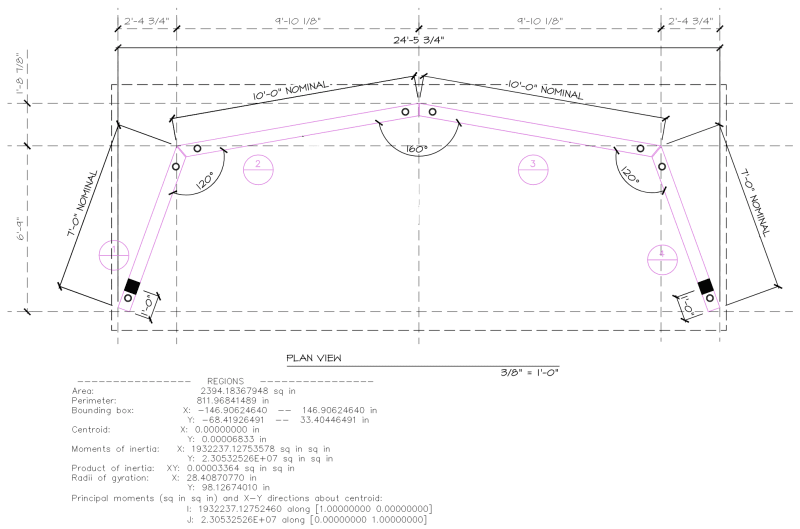
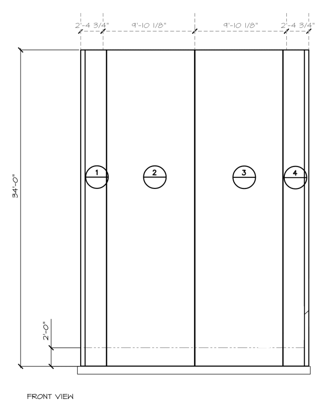
I have a project that came back on to my desk, and I have many reservations about what is proposed. I have included a plan view and elevation below. This is to be a climbing wall. It first started with the owners cardboard plan, and after I insisted, they found an EOR that is supposed to have experience in climbing walls. I do not think they looked at the feasibility of what our client suggested to them. Our client has never had a great appreciation for lateral loads or slenderness. I have not gotten far into this, and I would like some general thoughts. It is in a low seismic zone, so the load governing the problem is the 25psf wind load. The EOR has specified some gravity loads at the top of the panel, but those will not be a huge challenge if the general design is stable.

My problems:
1. 6" does not pass the general stink test in my mind.
2. Joints at intersections will need to be dry connections. They will be of paramount importance. I will never win the argument to field cast proper joints that would make my job far easier.
3. Base connections they will want will be simple dowels. Non-contact splices.
4. Only 4 pieces, so eng budget not great.

I can likely persuade them to go to an 8" wall, and add flanges to the ends of the wing panels. My question is do you think it is feasible or possible?

eng-tip1_ybia8x.png

eng-tip2_defwby.png
 
Replies continue below

Recommended for you

Interesting... I'm not sure how I'd go about analysing that structure... 6" walls, or 8" walls. Stability issues, and joints would be critical... maybe plate inserts and welds? I don't know. Is it exterior and are there wind loads on it? How many people? or, just assume a 20psf load 1' from the face. Loading could be interesting. Let us know what you decide to do with this... interesting.

So strange to see the singularity approaching while the entire planet is rapidly turning into a hellscape. -John Coates

-Dik
 
Thks dik. Yes, it is an exterior structure. I looked at it some today. I think I can basically simplify it to a three sided box. The EOR dwg does not show much other than wind loads. These things need WCB safety lines, and I had hoped they would show how many. Those are a large load at the very top of the wall. I think I will need three abutment walls to make it reasonable, so I suppose I need argue some more. I was hoping to avoid that since I have been vocal lately about overly complicated engineering problems for no reason.
 
I've designed a few climbing walls, but they were internal and not free standing. Used to rock climb when I was younger... no top roping and Grigris... I've got photos around here, somewhere, of my granddaughter on one of the walls I designed... that was two decades back.

So strange to see the singularity approaching while the entire planet is rapidly turning into a hellscape. -John Coates

-Dik
 
Can you add steel bracing on the inside. It would allow you to stabilize the panels and give a tension tie/comp strut when needed.

At 34' tall the last thing you want is for this to feel wobbly at the perception of the users.


At those panel widths, you may be in double tee range. Combine that with shear connections between panels and some creative base connection detailing?
 
Koot, they are not setup to make double tees, but the thought of adding stiffeners to each panel crossed my mind. I will have some fun discussion with the boss man. My current thought is to add the stiffeners sketched below. The axial force in the boundary member is about 30kip. Why they take on these silly jobs blows my mind.

Wrantler, I doubt they will have space on site for braces, but I plan to look into that. They do have a HSS tie at the top. That helps a little for one load case, but not the others.

dik, I have designed a few connections for interior climbing walls, but those were all anchored to a conventional bldg.

image_ng0wse.png
 
They climb on the concave side, right?

If so, can you build a braced frame from the outside and just bolt the panels to the frame?
 
The thin shell is elegant... This is one instance where I'd likely do a quick FEM analysis to see if uniform thickness 'shell' can do the work. Adding stiffeners as shown does little to affect the overall action, but does make the analysis easier.

So strange to see the singularity approaching while the entire planet is rapidly turning into a hellscape. -John Coates

-Dik
 
Brad805 said:
Koot, they are not setup to make double tees, but the thought of adding stiffeners to each panel crossed my mind.

I've made faux TT by casting wall panels and then CIP casting the ribs after the fact. This way, the ribs could be fatter things more amenable to OT base connections where desired. $$$ of course.

Brad805 said:
My current thought is to add the stiffeners sketched below.

Excellent, that's just what I'd envisioned when you mentioned the abutment walls. I feel that this is actually of some importance. I get the 3-sided building concept but, particularly without a proper diaphragm at the top, I feel that you would be prone to a possible buckling failure akin to distortional buckling in cold formed steel.
 
When bicycle rims went from being steel to aluminum, it was a game changer. That, not so much because of the material properties but, rather the ability to switch from a plain channel to an extruded tube with legs, as shown below. Wicked great torsionally of course. This kind of reminds me of that. Available panel widths and numerous other considerations will probably prohibit you from doing from something like this but, who knows, with the seed planted, perhaps it will find some way to germinate in fertile ground.

c01_rfqmsm.png
 
Dik, I created a FEM model yesterday. To determine if the boundaries buckle under load is not a simple FEM sadly. I would want an independent reviewer for that. There does seem to be some feasibility to it, but the slenderness of the boundary zones is off the charts and the connections concern me. If I could field cast the joints I would be a little more inclined. That said, I am a bit exhausted of these problems sucking up my time to solve.

Principle_stress_f96eib.png


Koot, field casting would wonderful, but it is like I am trying to steal their babies when I suggest such a thing. I did something somewhat similar to this not long ago. In that case I had a large precast column, and not some ridiculously slender element. For that base connection we welded rebar to an HSS and used anchor bolts. Piekko makes a very nice version of these, but they do not stock much in Montreal. Here I will have endless arguments why their typical base dowel is not a good idea. Lenton splice sleeves would be a nice idea as well.

JLNJ, yes, I believe they only use the inside surface. The dwgs are not stellar. A brace frame might work, but I will have to see.

I have sent my thoughts to them, and will see how this plays out.
 
start with how to handle or lift 34 ft long thin piece. Make sure that wont break when you tilt and lift. I think that will control.
 
Brad805 said:
Koot, field casting would wonderful, but it is like I am trying to steal their babies when I suggest such a thing.

Not field casting, plant casting as a second pour operation. Sorry, "CIP" was probably confusing in that regard.
 
Doublestud, an 8pt lift here is easy. We handle these all the time. That part is simple.

Koot, ahh, I get it. They would need to cast the stiffeners on day two.
 
Brad805 said:
These things need WCB safety lines, and I had hoped they would show how many.

Can you elaborate on the necessity for this? I was peripherally involved in an indoor climbing wall in Golden recently and I'm not sure that this was considered.
 
Use strongbacks for precast tilt up stuff... common problem

So strange to see the singularity approaching while the entire planet is rapidly turning into a hellscape. -John Coates

-Dik
 
Koot, when this started long ago another in the office went searching the regs. He found the discussion from the WCB below. At that point they were asking us to be the EOR, but we decided to decline. I had hoped they would engage one of the larger groups that does this type of work.

WCB-excerpt_gdjv5n.png
 
I do like Koots idea of a second pour and make them T beams... I have done this with the local precast company a few times.

You can them dowel the whole T section into the footing to give you a more rigid connection. Shouldnt be too much more expensive? It rly urks me when the owner is trying to save a few pennies so I can take more liability...
 
Brad, I worked for a precaster for 7 years. 8 lift pts was never easy for us. We didn't do may panels though. How many lift points are engaged when tilting up?
 
Status
Not open for further replies.

Part and Inventory Search

Sponsor