thirdjean
Aerospace
- Jun 3, 2013
- 1
Hello,
I'm new to designing mechanical components from scratch and therefore I'd like to ask you on how I can improve my knowledge for this.
This is the design that I'd like to figure out for:
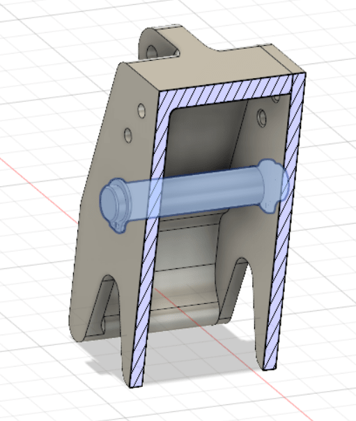
I have a shaft fitting into two holes on the frame (a two-piece assembly) which are about 40mm apart.
This shaft is intended to be relatively fixed to the frame, while another part with a PTFE-liner bushing rotates relative to this shaft.
This is a load-carrying important part of the assembly, thus a snug locational clearance fit has been selected.
Shaft = D10f7 [Recommendation from the bushing manufacturer]
Hole = D10M6 [Maximum clearance: 0.025 mm / Minimum clearance: 0.001 mm - Values close to that of a H7/h6 pair]
For the simplicity of the issue we can assume that we have a H7/h6 fit here.
I'm trying to determine the amount of positional tolerance I'd be able to allow on the two holes, each within their respective frame piece.
This in the end determines how much coaxiality I'd have on the assembly for the shaft installation.
If I observe the worst case of the shaft size and hole size, I'd have zero tolerance for misalignment of the holes....
A prototyping manufacturer asked me whether we can accept a +/- 0.1 mm positional tolerance for the frame pieces, and I'm lost...
What is the best way for me to assess how much positional / concentricity tolerance we can allow for these ISO-recommended fits?
I'd assume this is partially linked to manufacturability. I'm trying to know how much I can optimize my production cost without having to have an overly expensive clockwork part, nor having a fitting that cannot even be assembled properly.
Thank you so much for your help in advance!
I'm new to designing mechanical components from scratch and therefore I'd like to ask you on how I can improve my knowledge for this.
This is the design that I'd like to figure out for:
I have a shaft fitting into two holes on the frame (a two-piece assembly) which are about 40mm apart.
This shaft is intended to be relatively fixed to the frame, while another part with a PTFE-liner bushing rotates relative to this shaft.
This is a load-carrying important part of the assembly, thus a snug locational clearance fit has been selected.
Shaft = D10f7 [Recommendation from the bushing manufacturer]
Hole = D10M6 [Maximum clearance: 0.025 mm / Minimum clearance: 0.001 mm - Values close to that of a H7/h6 pair]
For the simplicity of the issue we can assume that we have a H7/h6 fit here.
I'm trying to determine the amount of positional tolerance I'd be able to allow on the two holes, each within their respective frame piece.
This in the end determines how much coaxiality I'd have on the assembly for the shaft installation.
If I observe the worst case of the shaft size and hole size, I'd have zero tolerance for misalignment of the holes....
A prototyping manufacturer asked me whether we can accept a +/- 0.1 mm positional tolerance for the frame pieces, and I'm lost...
What is the best way for me to assess how much positional / concentricity tolerance we can allow for these ISO-recommended fits?
I'd assume this is partially linked to manufacturability. I'm trying to know how much I can optimize my production cost without having to have an overly expensive clockwork part, nor having a fitting that cannot even be assembled properly.
Thank you so much for your help in advance!