gharli
Structural
- May 28, 2015
- 42
Hi All,
I am busy modelling a concrete tower with overall dimensions of 5.2m x 5.2m x 40m high.
The walls vary in thickness and shape.
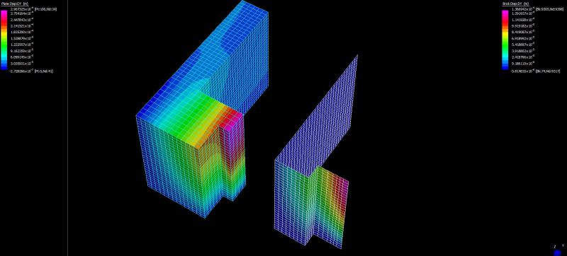
At one of the corners of the tower, the attached image shows the geometry thereof.
The centre lines of the tower walls are shown in red, yellow, green and blue.
The intention is to model the tower using Quad8 plate elements with the above mentioned lines being the centre lines.
My concern is the potential “thickness” overlap of the red, green and blue elements (shown in the bottom hatched image).
For all FEM gurus out there, is this a potential concern and if so, what modelling techniques should one incorporate?
The tower will be buried and hence subject to huge lateral and downdrag forces. In addition, without going into every last detail, these nibs are critical to the functioning of the tower.
I’m interested in all opinions, image is here:
[link ]Link[/url]
Thanks,
_________________
Jones & Wagener
I am busy modelling a concrete tower with overall dimensions of 5.2m x 5.2m x 40m high.
The walls vary in thickness and shape.
At one of the corners of the tower, the attached image shows the geometry thereof.
The centre lines of the tower walls are shown in red, yellow, green and blue.
The intention is to model the tower using Quad8 plate elements with the above mentioned lines being the centre lines.
My concern is the potential “thickness” overlap of the red, green and blue elements (shown in the bottom hatched image).
For all FEM gurus out there, is this a potential concern and if so, what modelling techniques should one incorporate?
The tower will be buried and hence subject to huge lateral and downdrag forces. In addition, without going into every last detail, these nibs are critical to the functioning of the tower.
I’m interested in all opinions, image is here:
[link ]Link[/url]
Thanks,
_________________
Jones & Wagener