EITInWI
Structural
- May 10, 2016
- 3
New to column and found this older post in research and looking for help. I am wondering if any of you know how to analyze the angle support given in the thread linked below.
Link
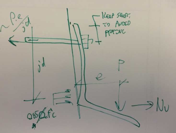
I am looking to design a new steel angle as a seat angle connection into an existing concrete beam to support form work for a concrete slab deck. The depth of the beam limits the design to be Option #1 in the attachment. My company has a designed spreadsheet for Option #2 to determine the tension on the anchor bolt, as well as the bending on the horizontal leg of the angle using the Flexible Method from PCI Design Handbook Precast and Precast Concrete, Sixth Ed. I am struggling with how to analyze the connection because there seems to be too many variables to solve for in the applied loading. Option #1 will not apply to Option #2 because instead of the vertical flange at the wall being in compression at the bottom, it will be moving away from the wall at the top of the vertical flange, and the bottom of the angle will be in compression. Also notice PCI accounts for a axial load Nu at the horizontal flange. Any help is appreciated, thanks.
I have attached a helpful picture that was included in the linked post and I have added my FBD in the same document.
Link
I am looking to design a new steel angle as a seat angle connection into an existing concrete beam to support form work for a concrete slab deck. The depth of the beam limits the design to be Option #1 in the attachment. My company has a designed spreadsheet for Option #2 to determine the tension on the anchor bolt, as well as the bending on the horizontal leg of the angle using the Flexible Method from PCI Design Handbook Precast and Precast Concrete, Sixth Ed. I am struggling with how to analyze the connection because there seems to be too many variables to solve for in the applied loading. Option #1 will not apply to Option #2 because instead of the vertical flange at the wall being in compression at the bottom, it will be moving away from the wall at the top of the vertical flange, and the bottom of the angle will be in compression. Also notice PCI accounts for a axial load Nu at the horizontal flange. Any help is appreciated, thanks.
I have attached a helpful picture that was included in the linked post and I have added my FBD in the same document.