Continue to Site

Eng-Tips is the largest engineering community on the Internet

Intelligent Work Forums for Engineering Professionals

  • Congratulations cowski on being selected by the Eng-Tips community for having the most helpful posts in the forums last week. Way to Go!

Hydraulic Valve Actuator using System Pressure

Status
Not open for further replies.

jartgo

Civil/Environmental
Oct 20, 2005
220
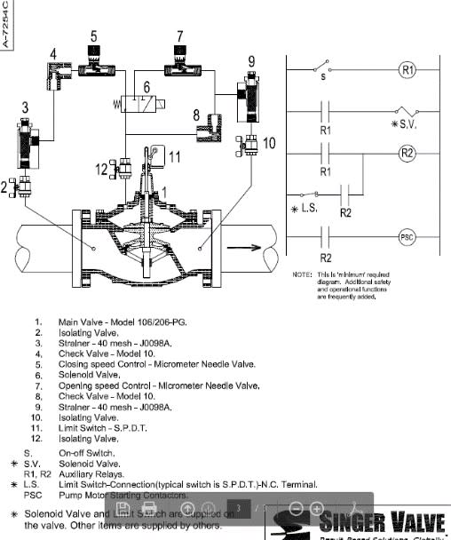
Can anyone point me to a general schematic of how this functions? I don’t necessarily need the actuators inner workings. I’m more interested in the connections to the system header. My specific situation is the application of a Pump control valve on a high service Pump. Thus I have (relatively) constant pressure on the distribution side and periods of no pressure on the Pump side. What I’m hoping is that the actuator will be connected to both sides, such that to shut the valve it will use distribution pressure and that to open the valve it will use discharge pressure, such that the valve won’t open if the pump isn’t generating an overcome pressure. Looking for a schematic that might illustrate this, or some other general working arrangement. Thanks in advance.
 
Replies continue below

Recommended for you

It looks like in this manual there is only one water inlet into the actuator. Is there then a power unit somewhere to generate a pressure higher than that provided from the water system? That is, I’m going to need to shut the valve against system pressure, therefore I would need a pressure greater than system pressure to act on the valve actuator (the diaphragm in the case of the link provided). Or is it just a difference in areas, where the area to close the valve is greater than the area to open the valve, thus with an equal pressure acting on each surface, the force to close is always greater than the force to open?

I was hoping I could tap the upstream side of the valve for valve open and the downstream side of the valve for valve shut...so that in the case of pump failure, the valve wouldn’t be able to open. Is this common or would this be an extraordinary arrangement?
 
Illustration which is more representative of the situation I’m dealing with. It will be a hydraulically actuated ball valve. I think I’ve determined that the pressure doesn’t need to be greater than system pressure because I’m not actually pushing against system pressure, just turning the valve shaft to move the ball into its position. My question stands whether I can connection the “valve open” side of the piston to the pump discharge side, such that the valve will not open if the pump has not generated pressure greater than system pressure?
 
 http://files.engineering.com/getfile.aspx?folder=6c5aa27b-7196-4ab0-831c-83a002afc89c&file=DBFD3997-75AF-478E-A5D5-0F1AC11D27B4.png
These valves work on line pressure. Solenoid valves are used to route the pressure to open or close the valve. The line pressure operates against a diaphragm. The operating force is based on the area of the diaphragm times the pressure. If you use a larger diaphragm on one side, lower pressure can be used to shut the valve against higher pressure.
 
jartgo, I am posting some more information. A ball valve will not work in this application. These valves are typically direct acting globe valves.

Note the spring in the valve which supplies additional closing force.


Refer to the schematic:

 
You can do lots of things with simple pilot valve relay technology.

There are valve vendors who will understand what you want, cla val are one but there are others who do this.

However it would be much easier to undertake if you did this via a small control system. If you've got a pump there surely you have an electrical supply also?

Come to think of it, what exactly is wrong with a simple non return valve? A spring plug valve would provide good shutoff capability and wouldn't open unless pressure on pump side exceeded header pressure.

Remember - More details = better answers
Also: If you get a response it's polite to respond to it.
 
It would help if we knew what you are trying to do? A standard pressure reducing valve opens with flow from the inlet (pump) when outlet pressure is lower than the setting of the pressure reducing pilot.
 
Pump Control Valve for a high service pump (pumping into distribution system).

It's a ball valve, similar to attached sketch.

Client has requested that the actuator operate using system pressure.

There will be no check valve and no pressure switch talking to the control valve.

I have currently designed an interlock so that if the pump "fails to start" the valve will emergency shut. What I'm trying to protect against now is the remote case of motor starts but pump isn't pumping (sheared shaft, etc.). I want to make sure the valve doesn't open. So what I'm proposing is that instead of a standard 4-way solenoid (inlet, valve open, valve shut, drain) there may be two 3-way solenoids whereas pump discharge pressure is used to open the valve and system pressure is used to shut the valve. I've updated the sketch to reflect what I think the end result will need to be and reattached it here. I should have it figured out next week and will let you know I came up with.
 
 http://files.engineering.com/getfile.aspx?folder=c4698289-a654-4882-a33c-0453ebf785db&file=PumpControl.pdf
jartgo,

your diagram makes no sense to me, neither does the sentence about no check valve.

Also what does "high service" mean??

You can do this using sets of relays and spring loaded valves, but if you have no check valve then once the valve is open you have equal pressure either side of the valve as the water flows backwards at high velocity back through the pump if the pump isn't running.

what you've drawn won't work I can tell you that much.

Like I said before a high quality check valve or two in series will do exactly what you want with no actuator at all....

what sort of pressure are we talking here?
And is that header full of water and at high pressure?

Remember - More details = better answers
Also: If you get a response it's polite to respond to it.
 
"Pump discharge pressure is used to open the valve and system pressure is used to shut the valve" describes a standard pressure reducing valve that does not require electric actuators. You can also add a check valve feature to the pressure reducing valve for an all in one valve.
 
schematic_gtivc7.jpg
 
Thanks all for your responses. I have determined that a valve control system very similar to the standard pump control valve that bimr posted, is what we will likely do. We are using a ball valve because it's important that we be able to control the opening and closing speeds whereas a check valve will not allow as much control. What we're wanting to do is to replicate what the Singer valve would do, albeit with more control over the opening and closing. It's a standard application (ball valve with hydraulic cylinder actuator) with a small change to get hydraulic pressure from two different places. Thanks to all for your contributions.
 
Status
Not open for further replies.

Part and Inventory Search

Sponsor