Continue to Site

Eng-Tips is the largest engineering community on the Internet

Intelligent Work Forums for Engineering Professionals

  • Congratulations cowski on being selected by the Eng-Tips community for having the most helpful posts in the forums last week. Way to Go!

How was this made? (pen pocket clip)

Status
Not open for further replies.

Papachabre

Mechanical
Jun 30, 2011
6
DSC_0102_dbfbiz.jpg


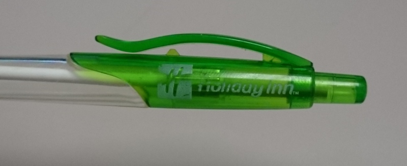
Does anyone know how this pen pocket clip could have been formed? It's all one piece, so either there was some seriously thin steel that formed it, or there's a secondary operation which seems pricey for a throwaway pen. It's parted parallel to the view.


Regards,
Bryan
 
Replies continue below

Recommended for you

Injection molded.

It is better to have enough ideas for some of them to be wrong, than to be always right by having no ideas at all.
 
Maybe you missed the text under the image? I'd guess that you're right - it was injection molded - but if it was formed in the shape that is pictured then the steel that went under the clip must have been blade-thin.


Regards,
Bryan
 
I don't know for sure, but I could see a secondary operation being involved. Part is molded with clip a bit higher than what you see, eject part, while part is still warm push clip to body.

Dan - Owner
URL]
 
Thanks for the reply. That's what I was thinking too. Maybe there's a fixture to make it consistent. I'd imagine it'd have to be automated somehow because pen molds have tons of cavities from what I've seen. I'll have to ask my supplier if he's got any ideas about it.


Regards,
Bryan
 
I would guess that during the molding process, there is more clearance between the clip and the body; the "L" shape of the clip will naturally warp inward a little as the material cools. It appears that the designer has varied the cross section along the length of the clip to "encourage" that tendency to warp. If you have a "Sharpie" marker on hand, the cap/clip is another good example; the tip of the clip actually touches the cap body. There is no way it was molded in that position.
 
@cowski - Good call on the Sharpie cap. I've got a few markers here at my desk and they all seem to have been made similarly. Controlled warp is a new concept for me - usually I try to avoid warping. I heard that there's a professor at a local university here that spoke to some members of the team about controlled warp before I started here. The only other thing I could think of is that maybe they let the caps cool on the core for a moment, and gravity pulls the clips down, then they strip them off once they've cooled. But that seems like it'd take too much machine time.

@ornerynorsk - Thanks for linking to that video. It was good to watch.


Regards,
Bryan
 
Notice the thin web where the clip is attached to the end cap. The Sharpie also has it. This should cool first, bringing the other end in to the body, while the thicker areas cool.

That, or it is just there for added strength.
 
I've got two Sharpies in my pocket.
Both show a parting line in the plane of symmetry.
I.e., the part of the mold that makes the exterior is split, so the clip can have most any profile, with no warping necessary.
The mold must be in three pieces, not two.

It's a small enough part that you could use a rotating rotary array of smallish molds that index through an injection machine and split the mold and eject the part at another station outside the molding machine proper.
I have no idea how they're actually molded, but I assert that possibilities exist for solutions other than a large planar array multicavity mold.


Mike Halloran
Pembroke Pines, FL, USA
 
I would guess they are moulded over a core for the inside diameter with side opening cheeks making the outer shape.

More than likely hot runner system to end of cap (small "pip" should be visible).

Stripper plate or sleeve ejection to get them off the cores.

Multi-cavity tooling. May be up to 128/256 parts per shot*.

H

* Chatting to a guy once who worked at a company making packaging stuff. They made two shot (rubber padded) aerosol caps. 350,000 per 24 hrs.

www.tynevalleyplastics.co.uk

It's ok to soar like an eagle, but weasels don't get sucked into jet engines.
 
Yes it seems like it's a 3-piece mold because there are two parting lines, but look at the left side of the clip part - the clip is nearly touching the body of the pen. That's all one piece, so to form it like that you'd need razor-thin steel to get between the plastic. I've never seen a tool with steel sections that thin which is why controlled warp seems like a possible solution.


Regards,
Bryan
 
Maybe, but the dimension of the clip normal to the parting line is fairly small, i.e., that part of the cavity is not very deep, so the delicate portion of the mold is cantilevered, but fairly well supported.

... so I wouldn't assume that post-mold deformation is necessary until I had tried making the part exactly as you see it, and had problems with mold durability.

Mike Halloran
Pembroke Pines, FL, USA
 
I wouldn't avoid plastic deformation when the plastic part is, er, plastic, either.

My favorite molder made some low-volume cylindrical collet type parts that would have required a collapsible core according to a traditional molder, because of internal teeth on the part. Given a back taper, they could be yanked off the core, leaving the collet arms splayed. The secondary operation comprised wrapping the arms with a rubber band to hold them in the correct place until they cooled.

It worked just fine with the intended resin, nylon/glass.
Some of the parts were too fragile to use in polyester/glass, tried just for fun.


Mike Halloran
Pembroke Pines, FL, USA
 
Thanks for the insight, Mike! I love hearing about innovative solutions like that.


Regards,
Bryan
 
Status
Not open for further replies.

Part and Inventory Search

Sponsor