Continue to Site

Eng-Tips is the largest engineering community on the Internet

Intelligent Work Forums for Engineering Professionals

  • Congratulations cowski on being selected by the Eng-Tips community for having the most helpful posts in the forums last week. Way to Go!

how to run a 480 Volt 3 phase motor on 240 volt single phase current 3

Status
Not open for further replies.

BlckHwk

Student
Jul 6, 2023
3
341919606_6640216952656343_7173080982211333692_n_mxf0xb.jpg


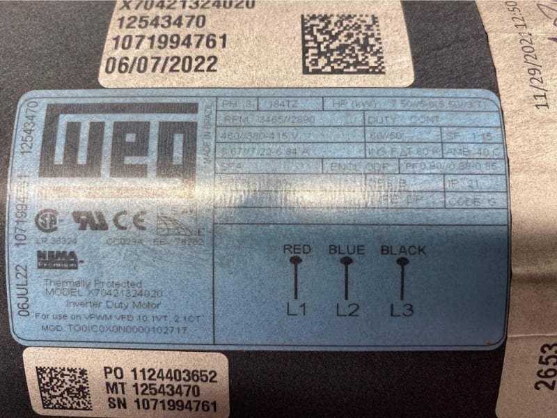
I would like to run this motor using 240 Volt single phase. I am thinking that I would require a VFD to go from single phase to three phase power but not sure about the voltage difference. The motor is going to be used to turn a tumbler which will have very low rotational RPM, between 15 and 25 would be optional, but it will be heavy so the motor will be required to supply a substantial torque load. The tumbler will be 8 foot in diameter, and hold 50 - 100 lbs of medium along with game furs. Total weight inside the tumbler is planned to be around 200 pounds. The tumbler itself is probably around 100/150 pounds, it has pillow block bearings on with axles on each side. It uses a drive sprocket and chain to turn the axle. I already plan on using gear reduction to slow the rotational speed, most likely adjusted with the VFD. My questions are, will this motor run using 240 volt 100 amp current? It does not need to turn at optional power or speed. If not is there a way to raise the home 240 volts to 480 volts which isn't overly pricey (approximately $500 or less)? What size or type VFD would I need? Any other information I should know?

Thanks,
Robin
 
Replies continue below

Recommended for you

Robin: INDEPENDENT OF OPERATING ON 240 V - 1 PH (input to drive) ... Look at your motor nameplate.
The motor is rated for 5.5 kW at 3465 rpm. It also has both a constant torque and a variable torque rating.
Constant torque (CT) range: 2 to 1 in speed, which means operating between 5.5 kW at 3465 rpm (nominal 460 V) and 2.75 kW at 1732 rpm (nominal 230 V). Both points equate to roughly 15 N.m torque load.
Variable torque (VT) range : 10 to 1 in speed, which means operating between 5.5 kW at 3465 rpm (nominal 460 V) and 0.055 kW at 346 rpm (nominal 46 V). This gives you a max torque of 15 N.m and a minimum torque of 1.5 N.m.

Is your chain drive capable of gearing your load up to the allowable motor speed(s)? (At max torque output and speed, that would be a gear ratio of 3465 to 25, or 138.6 to 1. If operating at the minimum constant torque speed, that would be 1762 to 25, or about 69 to 1!! Note that at minimum variable torque speed (346 rpm), you won't develop enough torque to get the process running - or keep it running - so the gear ratio is immaterial.)

Torque = force x moment arm.
Torque, in N.m = (150 lb + 200 lb) * (8/2 ft) = (1556 N) * (1.2 m) = 1867 N.m
... which is roughly 125 times the rated output of the motor at its full nameplate rating. This means two things:
1) You'll need AT LEAST that 138.6 to 1 gear reduction.
2) You'll need to find a way to provide 460 V/3 ph/60 Hz to the motor.

As to a possible drive: you might try the 2XD205R-OF (240 V in, 10 A out) shown at the following link.

Converting energy to motion for more than half a century
 
If 1/2 rated sped is enough, use a VFD rated for 240 Volt single phase input.
If you need full speed, use a VFD rated for 240 Volt or 480 Volt single phase input and a 240v/480V transformer.
If the transformer is on the input, it will be a single phase transformer.
If the transformer is on the VFD output it will be a three phase transformer. (240 Volt VFD)
A transformer on the output will provide good filtering but you probably don't need a filter unless there is a great distance between the VFD and the motor.

--------------------
Ohm's law
Not just a good idea;
It's the LAW!
 
Would adding a reduction gear to drop the gear ratio, such as GBPN-0403-160-AA171-197 from Anaheim automation which has a 160:1 ratio work to increase the torque? As for the drive if I'm understanding the information correctly it seems to be the type of thing that would work just need to try to find a price and place that sells them.

Sorry about all the questions it's just this is far from my field, I was an army pilot before I retired and now trying to work out something to make this motor turn. So thanks for the information.
 
waross based on what you posted I'm thinking my best approach would be to add a 240 VFD to this in order to change the single phase to three phase. I suspect this might provide enough power to turn the load. I will begin with the tumbler empty than add to it until either I have a full load or it no longer can turn it. If I am not able to turn it with enough of a load I'll add a 240 volt to 480 volt 3 phase step up transformer rated at 15 Kva. If I'm understanding things correctly that should be enough to start the motor and run it. Anything I'm missing or should watch for\test during the start up phase?

thanks again for all the help
 
waross said:
If 1/2 rated sped is enough, use a VFD rated for 240 Volt single phase input.

Doesn't the AC motor need the 480? Or is it a volts/hertz thing - 1/2 speed only needs 1/2 voltage?
 
You are correct, BrianE22.
The volts per hertz of a 480 Volt motor is 8 Volts per hertz.
At 240 Volts applied, the Hz must be 30 Hz or less.
Full torque at 1/2 speed.
Saves the price of a transformer.
You will still need a 7.5 HP rated VFD.
Set the motor parameters as:
Hz = 30
HP = 7.5/2 = 3.75 HP
Amps = full nameplate Amps.

This is a reverse twist on a trick that some compressor skid manufacturers have used.
The compressor required 100 HP.
Available voltage = 480 Volts.
A 240 Volt, 1760 RPM motor was used with a VFD outputting 480 Volts, 120 Hz.
Same torque, (same Hz per HP) at twice the speed = twice the HP.

But consider the tumbling action;
The rotation carries the material up the side of the vessel until it drops back.
Calculate the torque required to lift about 1/2 of the weight of the contents to the assumed tipping point. Assume the radius of the drum, as the contents are unlikely to be lifted past vertical.
Now use the torque and desired speed to calculate the HP required. (You may want to add a safety factor, possibly 2:1)
The required HP will probably be much less than 7.5 HP or 3.75 HP.
Look for a small gear-head motor or motor/gear reducer combination that will drive the tumbler.
A chain drive from a small sprocket on the gear reducer to a larger sprocket on the shaft of the tumbler will give you added gear reduction.
This may be more economical then a 7.5 HP VFD. If you want to adjust the speed permanently, change sprocket sizes.


--------------------
Ohm's law
Not just a good idea;
It's the LAW!
 
Reading a speed torque curve for a VFD driven motor:
I have always wondered why we don't see speed/torque curves for VFD drives.
Speed/torque curves are rated in motor speed.
For a 1760 RMP motor, the speed/torque curve looks like:
locked rotor torque at zero rpm.
Peak torque at about 1700 RPM.
Full load torque at 1760 RPM
Synchronous speed at 1800 RPM.
Now for a variable Volts and Hertz motor, the slip frequency or resulting slip RPM is more important.
If we relabel the speed/torque curve as a slip curve, it becomes.
synchronous speed at the applied frequency; Slip = zero RPM
Slip st full load = 40 RPM (1800RPM - 1760RPM = 40 RPM.
Slip at 200% load = 80 RPM (at or near peak torque)
With a properly designed VFD installation, a 1760 RPM motor will be operating in the 0 to 40 RPM slip range.
Torque boost will push the motor into the 40RPM to 80RPM slip range for short periods of time.

To convert a speed/torque curve to a slip RPM curve, simply subtract all of the RPM values from 1800 RPM.

1800 RPM = 0rpm slip
1760 RPM = 40 RPM slip.
1720 RPM = 80 RPM slip.
That is the only section of a classic speed/torque curve that you need for a VFD application.
Please add any comments, Gr8blu

--------------------
Ohm's law
Not just a good idea;
It's the LAW!
 
waross The "conversion" from typical speed-torque curve to "slip speed-torque" is correct. Almost all drives look at it just that way.
The other part of the consideration is to understand how the load is affected by torque with relation to speed, which is where the following two conditions come from. Note that these are the ONLY two conditions!

Constant torque: torque (or volt/hz) does not vary across the operating range. The motor will produce the same torque at every speed point - because the amplitude of current provided to the motor does not change. If you were to draw such a curve, it would be essentially straight lines as follows.
. . . zero torque at zero speed
. . . step change to rated torque at some (slightly above zero) speed (typically around 3 to 5% speed - note that "better" drives have a lower speed point)
. . . rated torque all the way to rated operating speed
To smooth out the step change, or to enable operation below 3% rated speed, drives employ the "voltage boost" approach.

Variable torque: torque (or volt/hz) varies across the operating range. The motor will not produce the same torque at every speed point - because the amplitude of current provided to the motor changes. If you were to draw such a curve, it would be a "custom" curve that may or may not follow typical affinity laws (power proportional to speed squared, for example).
. . . zero torque at zero speed
. . . step change to minimum torque at some (slightly above zero) speed (typically around 3 to 5% peed)
. . . rated torque only at rated operating speed
Voltage boost is not usually part of the operating profile.


Converting energy to motion for more than half a century
 
Status
Not open for further replies.

Part and Inventory Search

Sponsor