Continue to Site

Eng-Tips is the largest engineering community on the Internet

Intelligent Work Forums for Engineering Professionals

  • Congratulations cowski on being selected by the Eng-Tips community for having the most helpful posts in the forums last week. Way to Go!

How to Model Centrifugal Pump Frictional Loss calculation along the straight line and Branch in pipe 1

Status
Not open for further replies.

bmw318be

Mechanical
Jun 16, 2010
197
Hi Just wonder, understand that a centrifugal is not a constant flow device, have Some doubts on the parameter to considered in the frictional loss calculation.

Let say we have following system for simplicity

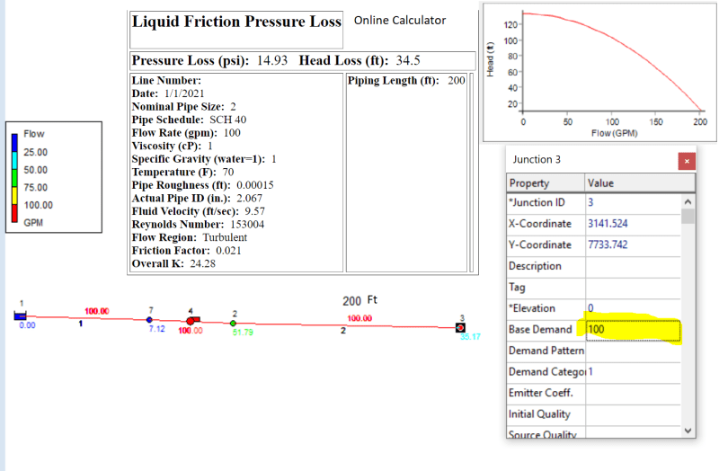
1. Horizontal line 200 Feet (Pipe 2 to 7 As illustration)
Epanet_Base_Demand_0_Flow_0_all_heg7b0.png

2. Elevation 0 m
3. Elbow 0
4. Tee 2
5. Pipe & Fitting size 2 Inch
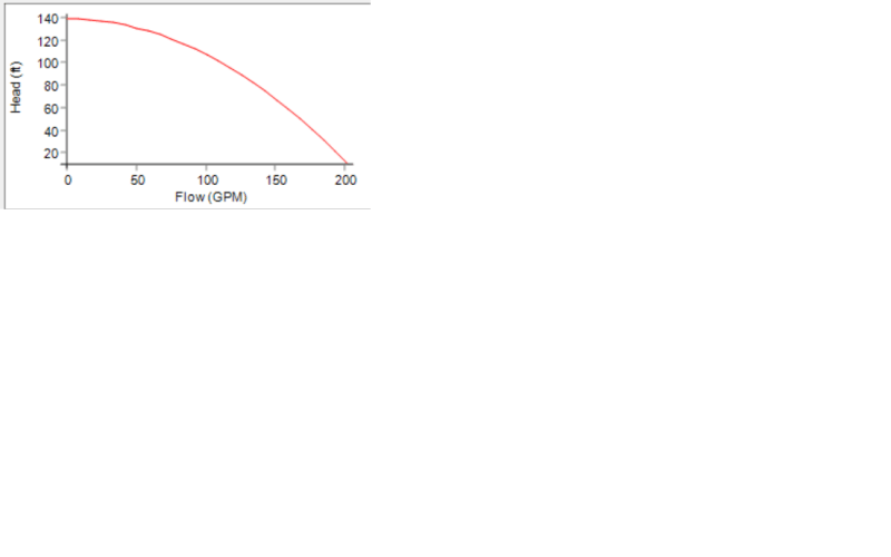
6. Centrifugal Pump 200 GPM Head 140 Feet

PC_200_GPM_140_Ft_owmx0f.png

Q1. In calculating pressure loss, what flow rate to be considered ?.

If we use maximum flow of 200 GPM, it may not be the case as when the pipe emptied, the flow would be 200 GPM and when it gradually filled the pipe, the friction loss would be accumulated and flow is reduced in respect to time.


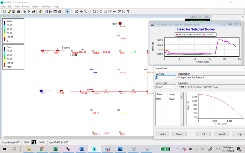
Q2. Using Epanet 2.2, the software is able to do modelling a flow system, we would the following Inputs

Can help me understand why there is a need for this node the total frictional losses are determined by the pump performance curve Flow and head.

1. On the Node
2. Flow Base demand

After we model this

1. Centrifugal Pump curve (Flow and Head) 200 GPM 140 Ft head
2. Pipe Size 2" All
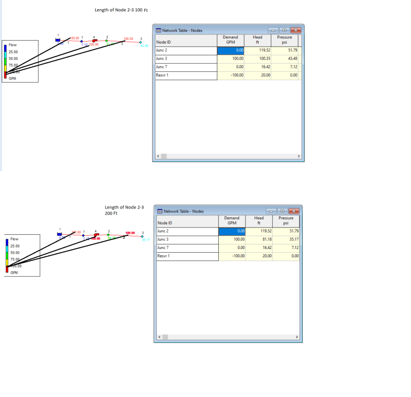
3. Pipe Length 100 Feet between Node
4. K value 0.85 Metal pipe
5. Elevation 0

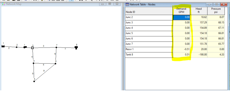
I got weird number when I entered Base demand 0 on all node

Epanet_Base_Demand_0_Flow_0_all_nh7kbz.png


Q3.
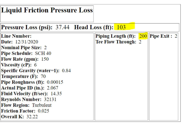
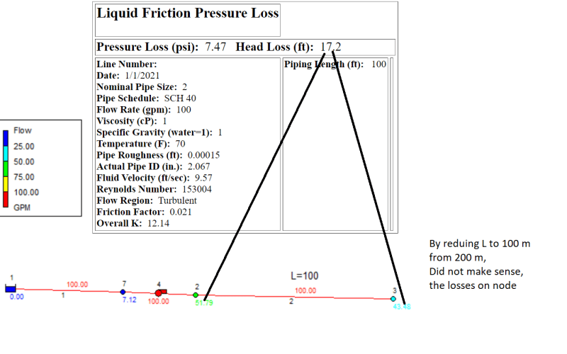
If modelling using the calculator based on assumption of 150 GPM moving Along 103 Feet Losses for 200 Feet length. In other words, there would still be a flow along the pipe line.

Frictional_Loss_Along_200_Ft_150_GPM_103_Feet_per_200_Feet_qza3fl.png
 
Replies continue below

Recommended for you

Your software Epanet is unknown to may of us. It will be helpful if you can rephrase the question starting from basics, e.g provide scheme with pipe data and then define operating conditions for calculation of friction losses.

Engineers, think what we have done to the environment !
 
Goutam,

My first question is 200 GPM 140 Feet head. What value we need to punch into the software or frictional loss calculation.


You know for centrifugal pump, it is not always constant along the frictional loss. So what is your consideration of flow that need to be considered here ?
 
EPAnet can only be used to model piping system that has a constant flowrate in all pipes. It will not model a filling pipe, a filling tank, or a draining pipe, or draining tank, or any other condition where flow in, into, or from any element is changing, or must change over time. You are modeling the system at a fixed time, thus flow rates cannot change. The software will calculate the flow going through the pump and select the appropriate head delivered by the pump.

Normally you set a constant supply flowrate at a source node, or nodes, and you set constant demands at various distribution nodes and the software calculates the flowrate in each pipe, pump, or other flow element. All demands and all distribution flow rates and the flows in every pipe, or pump remain constant for that one condition. If you want to see another solution, you change a demand, or distribution flow rate and run the program again.

Is it gasoline?

 
@bmw318be,
If EPAnet has capability to calculate friction drops only at constant flows (as 1503-44 says) then you need to vary the flow at a few discreet values and get the friction drops. You can plot a curve flow vs system resistance ( friction drop + static head) and superimpose it on pump Q-H curve. The intersection will give the operating flow and head. Graphical part can also be done using software like Excel or MATLAB.

Engineers, think what we have done to the environment !
 
Goutam,

You still not specifically mentioned at what flow rate from 0-200 GPM ?

If you use 200 GPM, definately in 2 inch pipe, the frictional loss going to be significant and it would be shut off and zero flow.

How can i plot this. As what I know, the pump would adapting to the frictional loss so question how you iterate this into a system curve, at what flowrate to be considered in the fitting losses ?
 
1503,
It is diesel

I think epanet has a time variable also right for 24 hours.

Because thought the software has ability to plot the centrifugal curve so are you implying we need to define the flow on the source node and define the demand flow at after the pump.

In other words, how this going to determine the frictional loss of the system on the centrifugal case where flow are varies as friction losses increases.

Any common practice how the frictional loss of system is determined when the pump is known ?
 
Katmar,

I see so I would take a different flow rate from

50, 70,90,120,140,180,200 and insert this into the software and draw the head.

the curve would be formed and intersection point is the flowrate.
 
Yes you must change the demand flowrate and run the software again each time.

Pump curve: The pump head being delivered to the fluid is the pump's (outlet puessure - inlet pressure) / fluid's density. Plot that number with the flow going through the pump for each run.

I'm not very familiar with the latest version of EPAnet. It may allow you to set different flowrates against clock time. But each clock time step will be a new run at the specified steady state flowrate. Each run will give results that are independent of the previous run and independent of the next run. It just solves different steady state models according to the steady state flow rate specified at the corresponding clock time. All flows in the system change instantly at any given clock time and are constant until the next clock time. Results between clock times do not change according to, or represent transient flow theory.

 
1503-44,

Thanks for various inputs, anyway this is something I screenshot another system, I just downloaded recently and still not able to figure out the parameter like node:

Anyway the time series is something like this of another system.

Epanet_System_1500_GPM_1000_Feet_Head_agbckc.png
 
It has calculated the pump curve using regression analysis between runs at different flow rates, just like you can do with Excel. Plot the points and select "show equation on chart".
OR maybe the user has entered the equation for the pump.

What exactly can you not figure out? What parameter?
 
Hi 1503-44,

Thanks, I have simplified my Hydraulic as below

Epanet System 100 GPM in 200 Feet 2 in length.

Case 1
Epanet_System_100_GPM_in_200_Feet_2_in_length_iutlow.png


I set Node 3 to have 100 GPM, not sure if this how it works, so in other words, the curve of the pump is redundant as it may run as constant flow of the 100 GPM Flow into node 2 and 3.

Some Doubts.

1. Why the node 2 is having 51.79 Ft and 35.17 Ft on node 3.

2. From the online calculator along the 200 Feet is having close to 34.5 Ft. It is close to Node 3, however, shall node 3 be close to 0 as it is exit ?

3. Not sure why node 2 is 51.79, can you help me understand this ?
Case 2 (Reducing the Pipe Length from pump to exit to 100 Feet)
Epanet_System_100_GPM_in_100_Feet_2_in_length_gmorvo.png


1. Why the node 2 is having 51.79 Ft and 43.48 Ft on node 3.
2. From Online calculator along 100 Feet is correctly 17.2 Feet losses.


Just curious, is this the limit of Epanet, they are not able to determine the Head and flow based on the PC curve

**
Unit US GPM, By default it is feet. The text is user input was corrected and not data input.
Unit_US_GPM_pmnxtq.png
 
It should work using the pump curve.

Several things are suspicious. I think there could be input data errors.
Pump should be adding approximately 100ft of head. What is the pump discharge node number and what is the head there?

What are head numbers at node 4 inlet and node 4 outlet?
Is there a long pipe between node 4 and node 2?

Are all EPAnet pipe ID exactly = 2.067"
If red numbers are lengths of pipe, than there is 300 ft total pipe.
Node 1 to 7= 100'
Node 7 to 2= 100' is that correct?
Node 2 to 3= 100'

Wondering why the node numbers are not 1,2,3,4,5,6,7
They may not need to be sequential, but it makes me think there could be configuration input errors. Also makes me think the file was incorrectly edited. Maybe node 7 or 4 are not actually where the drawing shows them? Are there two doubled pipes connecting any nodes? Drawing might not show that properly.

What is true length between nodes 7 and 4?
What is true length between nodes 4 and 2?

What are the blue numbers 0.0 at Node 1 and 7.12 at Node 7? If those are head, or pressures, than node 1 cannot be less than node 7, unless there is a change in elevation.


Hi Red us the flowrate
100 GPM

Node 2 to 3 is the only length .

All pipe is having 2 inch

Node 7 to 2 is just a pump node.

1 to 7 is 10 ft length
 
Of course. I saw that was 100gpm, but then I ... sorry.

ID 2.000" or 2.067" that's 100 ft of 3% difference?

7 to 2 is a pump node? Then what is 4? Also Pump curve says Pump is at "junction ID 3"

And the blue numbers???


ow,

hellID in epanet confirmed line is 2 inch pipe, anyway blue, green on node is in feet, head that u do not understand.

with 200 feet it is close to friction loss calculator yhe eoanet result at end of node hoeever changing to 109 fert, does not really make sense..

Pump curve just a screen shot thr curve plotted, and the node of 4 is set to have demand of 100 gpm means probably 100 gpm enter from pump, my guess :)


result did not make sense
 
Perhaps you have some reverse flow going on???

I think you should only set a supply to the system at node 1 of 100gpm and a demand from the system at node 3 of 100gpm.

One thing for certain is that the program has been used millions of times over many years now and does not appear to have significant errors, so first suspect GIGO and throughly check that input files and data is precise and fully correct.

 
1503-44,

The supply is 100 GPM is node 3, downstream is set on 100 GPM which I did.

Somehow the pressure on node, did not make sense. Please refer to screenshots of comparison below

100 Feet VS 200 Feet in 2 Inch Pipe

Epanet_System_100_GPM_in_100_Feet_200_Ft_2_in_length_fh14cs.png


My epanet file also attached below

** The text was typo unit, however the epanet software is in US unit, length was in feet.

Epanet_System_100_GPM_in_100_Feet_200_Ft_2_in_length_ohmrtv.png
 
bmw,

You are confusing metres with feet all the time and also psi with head.

So in your post on 1st jan the figures in green and turqoise are psi, but you appear to be comparing them to ft head. So they won't compare.

In the post above this makes sense to me.

For 100ft of pipe at 100 gpm you have a head loss of about 19 ft
For 200 ft (not m) at 100 gpm you have a head loss of about 38 ft.

So double the distance, double the head loss at the same flowrate. What is confusing about that?

EPANET is designed for a water network so simple pipes might not be so good.


Remember - More details = better answers
Also: If you get a response it's polite to respond to it.
 
Status
Not open for further replies.

Part and Inventory Search

Sponsor