Continue to Site

Eng-Tips is the largest engineering community on the Internet

Intelligent Work Forums for Engineering Professionals

  • Congratulations cowski on being selected by the Eng-Tips community for having the most helpful posts in the forums last week. Way to Go!

Help with lag screw lateral capacity calculation 3

Status
Not open for further replies.

gte447f

Structural
Dec 1, 2008
801
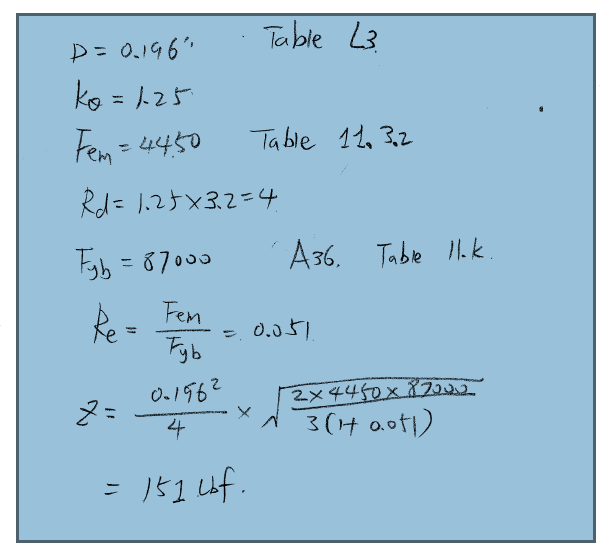
Anyone care to take a look through the attached calculation sheet for lateral capacity for a 1/4" diameter lag screw. I think there is an error in the calculation, but I cannot find it. In the attached calculation the controlling yield limit equation is Mode IV which is 105 lbs. However, the value listed in NDS Table 11K is 150 lbs. The online calculator at the American Wood Council website also calculates 150 lbs. Link

I thought maybe the other resources were possibly using the full shank diameter, D, whereas I have used the reduced body diameter, Dr, but I don't think that is the difference.

Can anyone spot where I have gone wrong?
 
 http://files.engineering.com/getfile.aspx?folder=c02d08da-1114-4e02-841b-0fa9cdf1d2c3&file=wood_connection_-_1-4_diameter_-_lag_screw_-_lateral_load_-_steel_side_member.pdf
Replies continue below

Recommended for you

bridgebuster, thanks for sharing your spreadsheet. It's reassuring that we get similar values. It's not so reassuring that the NDS tables and the AWC calculator give almost 50% higher values.

Curiously, I could not get your spreadsheet to return 107 as you did. Instead I get a marginally higher value of around 114 when I plug my values into your spreadsheet (attached). But 107 or 114 is still much closer to my calculation sheet value of 105 than the 150 in the NDS table.
 
 http://files.engineering.com/getfile.aspx?folder=fb977fc5-dcfd-4800-992b-7cad3a7b9431&file=05NDS.BOLTS.pdf
The number you want probably depends on the type of wood. US Forest Products lab in Madison likely has a lot of info on this subject.
 
Thanks for your input oldestguy. Per the NDS yield limit equations, the lateral capacity of dowels like nails, bolts, lag screws, etc. is dependent on the specific gravity of the wood species (0.5 for an LVL per the manufacturer in the case of my connection). Both my calc and bridgebuster's have input for the specific gravity of the wood members.
 
Is the NDS value LRFD whereas yours are ASD? I see a factor difference of 1.4 here in 150/107 = 1.4.

Mike McCann, PE, SE (WA)


msquared48, I think that's just a helluva coincidence. I think the NDS reference design values should be ASD. To convert them to LRFD you have to multiply by a format conversion factor, Kf=3.32, and the resistance factor, phi=0.65.
 
I did a rough calculation and the 151lbf seems right.

sketch_z7kqjv.png
 
Shu Jiang, thank you for contributing. I see 2 differences between my calc and yours. First, you use D=0.196" from Table L3. I use D=0.173" from Table L2. Table L3 is for wood screws and Table L2 is for lag screws, so I believe your calc is in error in this regard. Second, you use 87,000 psi under the radical which is the dowel bearing strength for steel (i.e. 1.5 times Fu of 58ksi). I use 70,000 psi under the radical which is the bending yield strength, Fy, for 1/4" diameter steel dowels. I checked the yield limit equation for mode IV in Breyor's book and in NDS Table 11.3.1A and both have Fy under the radical, so I believe your calc is in error in this regard also. Do others agree? If so, it is certainly strange that the compounding effect of these two errors results in the value presented in NDS Table 11K.
 
This has been bothering me and I finally had a chance to look at it a little closer. I think the discrepancy might me in the Rd factor (reduction for angle to grain). Your equation shows it as 3.2Ko, but in the footnotes of the NDS Table 11.3.1B there is a note that reads

"For threaded fasteners where nominal diameter is greater than or equal to 0.25" and root diameter is less than 0.25 Rd = KD*Ko"

This would change the reduction factor to 2.2Ko yielding a value for Mode IV of 3.2/2.2*105 = 152#

With a 1/4"Ø lag you are smack dab in the middle between lag screws and wood screws and pushing the limits of applicability of the various equations, hence the footnote. Just for kicks, take a look at the value for #12 wood screw (Dr = 0.171) thru 3 ga (0.239") side plate into wood. Z=201# even though the root diameter and plate are virtually identical to your lag screw case(you get an additional 30%).

With a material like wood, it is difficult to get equations that work for all cases that are not overly complicated, so there will be some overlap. Unless you have an oddball case I say take the table values and run with them.
 
It is funny how low the design values are for lags and thru bolts in wood. A 10d nail has more capacity than a 1/4" lag. (4)10d has about the same as a 1/2" thru bolt. Let's face it, something ain't right.
 
RWW0002, Thanks for digging into this. I think your explanation must be the right one. I had not noticed the footnote and the special case for Rd=Kd*Ktheta for "transition" diameters.

XR250, I am with you... I am sometimes surprised at how low the design values are for lag screws and thru bolts in wood.
 
Status
Not open for further replies.

Part and Inventory Search

Sponsor